

Optical Spectroscopy Instrumentation Design
173
Raman test.” Assuming the water sample is of very high purity and is contained in a fully
sealed cuvette to prevent ingress of contaminants, this test can be reliable at wavelengths
below 400 nm. The reason for this is that the intensity of the Raman signal changes by 1/λ
4
,
thus at longer wavelengths of excitation the signal levels are considerably reduced. For
many manufacturers the water Raman test and the resulting SNR become a measure of their
instrument performance guarantee. Not all manufacturers record this signal nor calculate the
resulting SNR in the same manner, so considerable care should be applied in the exact definitions and comparison. Presented in Table 5.5 are some suggested measurement conditions
and analysis methods for routine assessment of the instrument performance in terms of total
signal and water Raman SNR. A water Raman spectra is shown in Figure 5.17.
5.4.9 Linearity, Signal to Noise, and Dynamic Range
The dynamic range of a spectroscopic instrument is of considerable importance because if
allows the measurement of both weak and strong signals that might be closely spaced in
wavelengths. There are several ways to consider the dynamic range and it is often quoted
in a simple way that might not always reflect reality. For any instrument, the key figures of
merit are the maximum signal that can be measured without distortion and what the noise
level is. This gives a SNR maximum level, or the dynamic range of the instrument.
For a fluorimeter instrument the noise level is determined by several factors:
The noise level from the photomultiplier detector
•
The stability of the xenon lamp, that is, light fluctuation or noise in the excitation light
•
level
The stray light performance of the instrument at the wavelengths of interest
•
Single-photon counting fluorimeters exhibit exceptional dynamic ranges compared to their
analog counterparts. Typical photon counters in modern fluorimeters are capable of up to
100 Mega counts per second (Mcps) if the signal is repetitive. Ideally, two photon events
are identified by appropriate discriminators and counted as two events. However, in a practical situation two problems exist. First, the incoming photon rate is random and as such
the available counting rate is reduced, as we need to be able to distinguish between photon
pulses; and second, the pulse width of each photon pulse is of finite value because of the
detector time responses. Therefore, it is necessary to distinguish between two pulses, that
is, the pulse-pair resolution. If the time between photon pulses is less than or equal to the
time to resolve the two photon pulses then they look like a “single” event and the signal
is lost. This is the time after a first pulse within which the system cannot distinguish the
next photon pulse, that is, a pile up phenomenon and is referred to as the dead-time of the
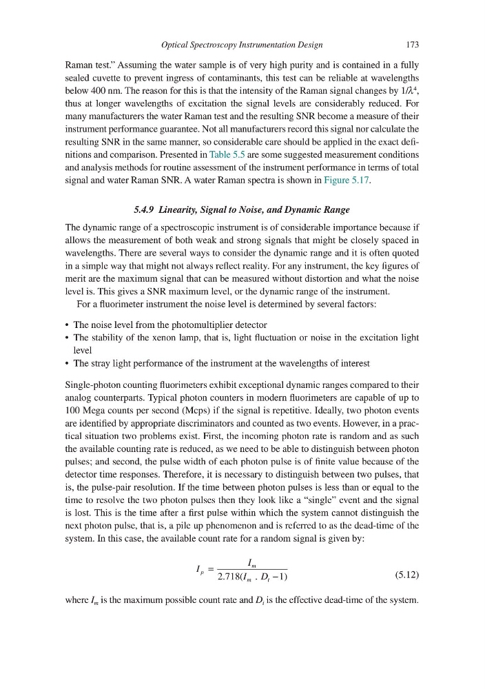
system. In this case, the available count rate for a random signal is given by:
I
I
I . D
p
m
m
t
= 2.718(
1)
−
(5.12)
where I m is the maximum possible count rate and D i is the effective dead-time of the system.
173
Raman test.” Assuming the water sample is of very high purity and is contained in a fully
sealed cuvette to prevent ingress of contaminants, this test can be reliable at wavelengths
below 400 nm. The reason for this is that the intensity of the Raman signal changes by 1/λ
4
,
thus at longer wavelengths of excitation the signal levels are considerably reduced. For
many manufacturers the water Raman test and the resulting SNR become a measure of their
instrument performance guarantee. Not all manufacturers record this signal nor calculate the
resulting SNR in the same manner, so considerable care should be applied in the exact definitions and comparison. Presented in Table 5.5 are some suggested measurement conditions
and analysis methods for routine assessment of the instrument performance in terms of total
signal and water Raman SNR. A water Raman spectra is shown in Figure 5.17.
5.4.9 Linearity, Signal to Noise, and Dynamic Range
The dynamic range of a spectroscopic instrument is of considerable importance because if
allows the measurement of both weak and strong signals that might be closely spaced in
wavelengths. There are several ways to consider the dynamic range and it is often quoted
in a simple way that might not always reflect reality. For any instrument, the key figures of
merit are the maximum signal that can be measured without distortion and what the noise
level is. This gives a SNR maximum level, or the dynamic range of the instrument.
For a fluorimeter instrument the noise level is determined by several factors:
The noise level from the photomultiplier detector
•
The stability of the xenon lamp, that is, light fluctuation or noise in the excitation light
•
level
The stray light performance of the instrument at the wavelengths of interest
•
Single-photon counting fluorimeters exhibit exceptional dynamic ranges compared to their
analog counterparts. Typical photon counters in modern fluorimeters are capable of up to
100 Mega counts per second (Mcps) if the signal is repetitive. Ideally, two photon events
are identified by appropriate discriminators and counted as two events. However, in a practical situation two problems exist. First, the incoming photon rate is random and as such
the available counting rate is reduced, as we need to be able to distinguish between photon
pulses; and second, the pulse width of each photon pulse is of finite value because of the
detector time responses. Therefore, it is necessary to distinguish between two pulses, that
is, the pulse-pair resolution. If the time between photon pulses is less than or equal to the
time to resolve the two photon pulses then they look like a “single” event and the signal
is lost. This is the time after a first pulse within which the system cannot distinguish the
next photon pulse, that is, a pile up phenomenon and is referred to as the dead-time of the
system. In this case, the available count rate for a random signal is given by:
I
I
I . D
p
m
m
t
= 2.718(
1)
−
(5.12)
where I m is the maximum possible count rate and D i is the effective dead-time of the system.