

13—2.
THE CYCLOTRÛN
293
13—2.
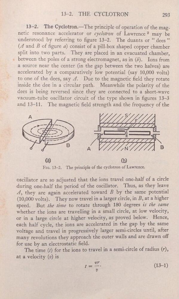
The Cyclotron.—The principle of operation of the magnetic resonance accelerator or cyclotron of Lawrence2 may be
understood by referring to gure 13—2. The duants or “.dees ”
(Â and B of gure a) consist of a pill-box shaped copper chamber
'
’
split into two parts. They are placed in an evacuated chamber,
_
_
between the poles of a strong electromagnet, as in (5). Ions from
a source near the center (in the gap between the two halves) are
-
accelerated by a comparatively low potential (say 10,000 volts)
to one of the dees, say Â.
Due to the magnetic eld they rota-te
inside the dee in a circular path. Meanwhile the
of the
—
‘
_
dees is being reversed since they are connected to a short-wave
vacuum—tube oscillator circuit of the type shown in gures _13—3
and 13—11.
The magnetic eld strength and the frequency of the
.
s/
'
A
4
_
_
F/
_I/
_
_
"‘"
.
_
B
A
/N
B
(a)
(b)
‘
-
FIG. 13—2.
The principle of the cyclotron of Lawrence.
.
oscillator are so adjusted that the ions travel one—half
of a circle
during one-half the period of the oscillator. -Thus, as they leave
_'
Â, they are again accelerated toward B by the same potential
_
__
'
(10,000volts).
They now travel in a larger circle,
in B, at a higher
speed.
But the time to rotate through
180 degrees .is"tlze same
=
whether the ions are travelling in a small circle, at low veloC1ty,
_
'
or in a large Circle at higher velocity, as‘ proved below. Hence,
_.
each half
ions are accelerated in
the gap by the same
voltage and travel in pfogreSsively larger semi-circles until, after
many revolutions they approachthe
outer wal—ls and are drawn off
'
for use by an electrostatic eld… '
—
The time (t) for the;ions_to travel in a semi—circle of
(r),
at aveloc'ity(v)
,
'
'
'
’
THE CYCLOTRÛN
293
13—2.
The Cyclotron.—The principle of operation of the magnetic resonance accelerator or cyclotron of Lawrence2 may be
understood by referring to gure 13—2. The duants or “.dees ”
(Â and B of gure a) consist of a pill-box shaped copper chamber
'
’
split into two parts. They are placed in an evacuated chamber,
_
_
between the poles of a strong electromagnet, as in (5). Ions from
a source near the center (in the gap between the two halves) are
-
accelerated by a comparatively low potential (say 10,000 volts)
to one of the dees, say Â.
Due to the magnetic eld they rota-te
inside the dee in a circular path. Meanwhile the
of the
—
‘
_
dees is being reversed since they are connected to a short-wave
vacuum—tube oscillator circuit of the type shown in gures _13—3
and 13—11.
The magnetic eld strength and the frequency of the
.
s/
'
A
4
_
_
F/
_I/
_
_
"‘"
.
_
B
A
/N
B
(a)
(b)
‘
-
FIG. 13—2.
The principle of the cyclotron of Lawrence.
.
oscillator are so adjusted that the ions travel one—half
of a circle
during one-half the period of the oscillator. -Thus, as they leave
_'
Â, they are again accelerated toward B by the same potential
_
__
'
(10,000volts).
They now travel in a larger circle,
in B, at a higher
speed.
But the time to rotate through
180 degrees .is"tlze same
=
whether the ions are travelling in a small circle, at low veloC1ty,
_
'
or in a large Circle at higher velocity, as‘ proved below. Hence,
_.
each half
ions are accelerated in
the gap by the same
voltage and travel in pfogreSsively larger semi-circles until, after
many revolutions they approachthe
outer wal—ls and are drawn off
'
for use by an electrostatic eld… '
—
The time (t) for the;ions_to travel in a semi—circle of
(r),
at aveloc'ity(v)
,
'
'
'
’