

double-scatter and non-linearities in the gravity waves on the sea surface, and the
first-order Bragg energy is used to normalize the second-order measurements
(Barrick 1977). Because this analysis uses the second-order energy, which is
typically [10 db below the first-order signals, it is generally limited by signal-tonoise ratios, and the spatial coverage is much reduced from that observed for
surface currents and wind directions, which use first-order echoes (Heron and
Heron 1998).
13.2.2 System Comparison
As mentioned, the two dominant HF ocean radar systems currently in use are the
phased-array and the crossed-loop direction-finding system. An example of a
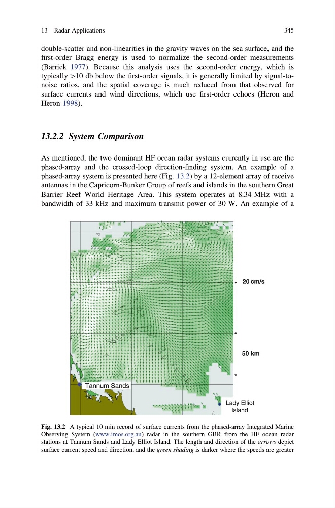
phased-array system is presented here (Fig. 13.2) by a 12-element array of receive
antennas in the Capricorn-Bunker Group of reefs and islands in the southern Great
Barrier Reef World Heritage Area. This system operates at 8.34 MHz with a
bandwidth of 33 kHz and maximum transmit power of 30 W. An example of a
50 km
20 cm/s
Lady Elliot
Island
Tannum Sands
Fig. 13.2 A typical 10 min record of surface currents from the phased-array Integrated Marine
Observing System (www.imos.org.au) radar in the southern GBR from the HF ocean radar
stations at Tannum Sands and Lady Elliot Island. The length and direction of the arrows depict
surface current speed and direction, and the green shading is darker where the speeds are greater
13 Radar Applications
345
first-order Bragg energy is used to normalize the second-order measurements
(Barrick 1977). Because this analysis uses the second-order energy, which is
typically [10 db below the first-order signals, it is generally limited by signal-tonoise ratios, and the spatial coverage is much reduced from that observed for
surface currents and wind directions, which use first-order echoes (Heron and
Heron 1998).
13.2.2 System Comparison
As mentioned, the two dominant HF ocean radar systems currently in use are the
phased-array and the crossed-loop direction-finding system. An example of a
phased-array system is presented here (Fig. 13.2) by a 12-element array of receive
antennas in the Capricorn-Bunker Group of reefs and islands in the southern Great
Barrier Reef World Heritage Area. This system operates at 8.34 MHz with a
bandwidth of 33 kHz and maximum transmit power of 30 W. An example of a
50 km
20 cm/s
Lady Elliot
Island
Tannum Sands
Fig. 13.2 A typical 10 min record of surface currents from the phased-array Integrated Marine
Observing System (www.imos.org.au) radar in the southern GBR from the HF ocean radar
stations at Tannum Sands and Lady Elliot Island. The length and direction of the arrows depict
surface current speed and direction, and the green shading is darker where the speeds are greater
13 Radar Applications
345