

pressure (in the case of a sound receiver). As an example, lead zirconate crystals
will generate piezoelectricity when their static structure is deformed by *0.1 %
or, conversely, will change *0.1 % of their static dimension when an external
electric field is applied. To harness this physical property, the granular material is
fused into a ceramic-like block that can be moulded into any shape, and when heat
(*120 °C, the Curie temperature; Medwin and Clay 1998) and a DC polarizing
voltage are applied the block becomes an assemblage of tetrahedron crystals with a
preferred axis. Depending on the orientation of the electrodes, this causes the
material to be piezoelectric for shear or compression, which thereby defines the
type of transducer and its operating design.
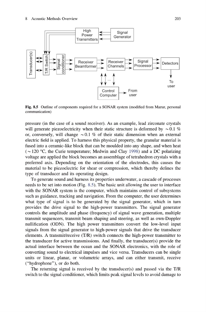
To generate sound and harness its properties underwater, a cascade of processes
needs to be set into motion (Fig. 8.5). The basic unit allowing the user to interface
with the SONAR system is the computer, which maintains control of subsystems
such as guidance, tracking and navigation. From the computer, the user determines
what type of signal is to be generated by the signal generator, which in turn
provides the drive signal to the high-power transmitters. The signal generator
controls the amplitude and phase (frequency) of signal wave generation, multiple
transmit sequencers, transmit beam shaping and steering, as well as own-Doppler
nullification (ODN). The high power transmitters convert the low-level input
signals from the signal generator to high-power signals that drive the transducer
elements. A transmit/receive (T/R) switch connects the high-power transmitter to
the transducer for active transmissions. And finally, the transducer(s) provide the
actual interface between the ocean and the SONAR electronics, with the role of
converting sound to electrical impulses and vice versa. Transducers can be single
units or linear, planar, or volumetric arrays, and can either transmit, receive
(‘‘hydrophone’’), or do both.
The returning signal is received by the transducer(s) and passed via the T/R
switch to the signal conditioner, which limits peak signal levels to avoid damage to
Fig. 8.5 Outline of components required for a SONAR system (modified from Mazur, personal
communication)
8 Acoustic Methods Overview
203
will generate piezoelectricity when their static structure is deformed by *0.1 %
or, conversely, will change *0.1 % of their static dimension when an external
electric field is applied. To harness this physical property, the granular material is
fused into a ceramic-like block that can be moulded into any shape, and when heat
(*120 °C, the Curie temperature; Medwin and Clay 1998) and a DC polarizing
voltage are applied the block becomes an assemblage of tetrahedron crystals with a
preferred axis. Depending on the orientation of the electrodes, this causes the
material to be piezoelectric for shear or compression, which thereby defines the
type of transducer and its operating design.
To generate sound and harness its properties underwater, a cascade of processes
needs to be set into motion (Fig. 8.5). The basic unit allowing the user to interface
with the SONAR system is the computer, which maintains control of subsystems
such as guidance, tracking and navigation. From the computer, the user determines
what type of signal is to be generated by the signal generator, which in turn
provides the drive signal to the high-power transmitters. The signal generator
controls the amplitude and phase (frequency) of signal wave generation, multiple
transmit sequencers, transmit beam shaping and steering, as well as own-Doppler
nullification (ODN). The high power transmitters convert the low-level input
signals from the signal generator to high-power signals that drive the transducer
elements. A transmit/receive (T/R) switch connects the high-power transmitter to
the transducer for active transmissions. And finally, the transducer(s) provide the
actual interface between the ocean and the SONAR electronics, with the role of
converting sound to electrical impulses and vice versa. Transducers can be single
units or linear, planar, or volumetric arrays, and can either transmit, receive
(‘‘hydrophone’’), or do both.
The returning signal is received by the transducer(s) and passed via the T/R
switch to the signal conditioner, which limits peak signal levels to avoid damage to
Fig. 8.5 Outline of components required for a SONAR system (modified from Mazur, personal
communication)
8 Acoustic Methods Overview
203