

88
Marian de Vries and Peter van Oosterom
of the boundaries shared between scales; and (ii) boundaries are always drawn at
the highest detail level (all points are used, even if it would not be meaningful for
a given scale). Therefore, the tGAP structure was developed: a topological structure
with faces and edges and no duplicate geometries, but using the same principle as
the original GAP-tree – coarse representations of an area are refined by more detailed ones. A more in-depth explanation and motivation of the steps taken in the
development of the tGAP structure can be found in [23].
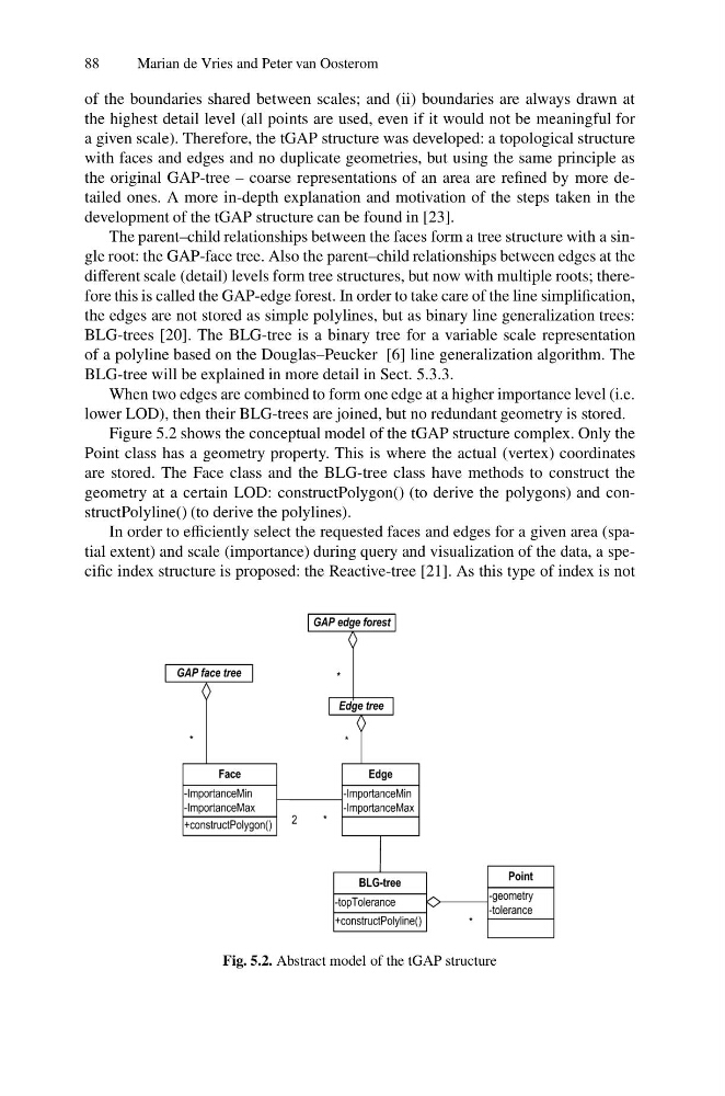
The parent–child relationships between the faces form a tree structure with a single root: the GAP-face tree. Also the parent–child relationships between edges at the
different scale (detail) levels form tree structures, but now with multiple roots; therefore this is called the GAP-edge forest. In order to take care of the line simplification,
the edges are not stored as simple polylines, but as binary line generalization trees:
BLG-trees [20]. The BLG-tree is a binary tree for a variable scale representation
of a polyline based on the Douglas–Peucker [6] line generalization algorithm. The
BLG-tree will be explained in more detail in Sect. 5.3.3.
When two edges are combined to form one edge at a higher importance level (i.e.
lower LOD), then their BLG-trees are joined, but no redundant geometry is stored.
Figure 5.2 shows the conceptual model of the tGAP structure complex. Only the
Point class has a geometry property. This is where the actual (vertex) coordinates
are stored. The Face class and the BLG-tree class have methods to construct the
geometry at a certain LOD: constructPolygon() (to derive the polygons) and constructPolyline() (to derive the polylines).
In order to efficiently select the requested faces and edges for a given area (spatial extent) and scale (importance) during query and visualization of the data, a specific index structure is proposed: the Reactive-tree [21]. As this type of index is not
Fig. 5.2. Abstract model of the tGAP structure
Marian de Vries and Peter van Oosterom
of the boundaries shared between scales; and (ii) boundaries are always drawn at
the highest detail level (all points are used, even if it would not be meaningful for
a given scale). Therefore, the tGAP structure was developed: a topological structure
with faces and edges and no duplicate geometries, but using the same principle as
the original GAP-tree – coarse representations of an area are refined by more detailed ones. A more in-depth explanation and motivation of the steps taken in the
development of the tGAP structure can be found in [23].
The parent–child relationships between the faces form a tree structure with a single root: the GAP-face tree. Also the parent–child relationships between edges at the
different scale (detail) levels form tree structures, but now with multiple roots; therefore this is called the GAP-edge forest. In order to take care of the line simplification,
the edges are not stored as simple polylines, but as binary line generalization trees:
BLG-trees [20]. The BLG-tree is a binary tree for a variable scale representation
of a polyline based on the Douglas–Peucker [6] line generalization algorithm. The
BLG-tree will be explained in more detail in Sect. 5.3.3.
When two edges are combined to form one edge at a higher importance level (i.e.
lower LOD), then their BLG-trees are joined, but no redundant geometry is stored.
Figure 5.2 shows the conceptual model of the tGAP structure complex. Only the
Point class has a geometry property. This is where the actual (vertex) coordinates
are stored. The Face class and the BLG-tree class have methods to construct the
geometry at a certain LOD: constructPolygon() (to derive the polygons) and constructPolyline() (to derive the polylines).
In order to efficiently select the requested faces and edges for a given area (spatial extent) and scale (importance) during query and visualization of the data, a specific index structure is proposed: the Reactive-tree [21]. As this type of index is not
Fig. 5.2. Abstract model of the tGAP structure