

Design of nitrifying plants
Nitrification rate rA,NH4 (g N/(m 2 ·d))
Type of wastewater
min.
max.
Tannery
2.35
2.61
Fertilizer indus try
2.36
2.67
Leachate
2.42
2.66
Municipal wastewater, 1
2.03
2.56
Municipal wastewater, 2
1.69
1.82
Municipal wastewater, 3
2.20
2.56
Municipal wastewater, Btisnau
4.61
4.84
Combined sewer overflow
1.53
1.97
Gas works
2.25
2.36
Tar production
004
0.12
Table 6.6
Mean removal rates for nitrifying biofilm plants at 20°C /9 I.
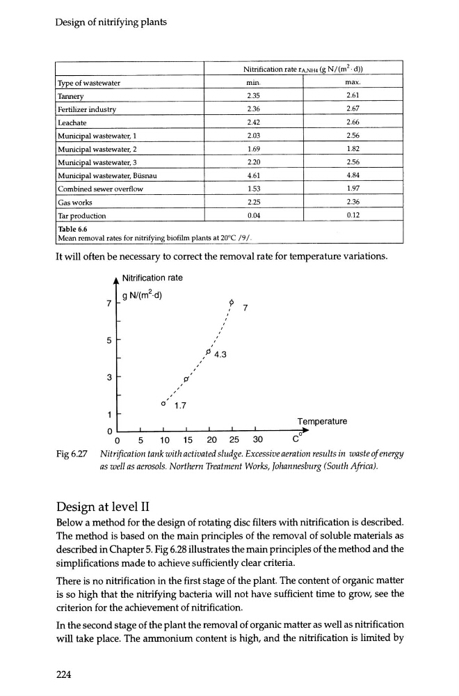
It will often be necessary to correct the removal rate for temperature variations.
Nitrification rate
g N/(m 2 ·d)
9
7
7
'
'
'
'
5
'
,P 4.3
3
>f
'
'
'
'
0
1.7
Temperature
0
co
0
5
10
15
20
25
30
Fig 6.27 Nitrification tank with activated sludge. Excessive aeration results in waste of energy
as well as aerosols. Northern Treatment Works, Johannesburg (South Africa).
Design at level II
Below a method for the design of rotating disc filters with nitrification is described.
The method is based on the main principles of the removal of soluble materials as
described in Chapter 5. Fig 6.28 illustrates the main principles of the method and the
simplifications made to achieve sufficiently clear criteria.
There is no nitrification in the first stage of the plant. The content of organic matter
is so high that the nitrifying bacteria will not have sufficient time to grow, see the
criterion for the achievement of nitrification.
In the second stage of the plant the removal of organic matter as well as nitrification
will take place. The ammonium content is high, and the nitrification is limited by
224
Nitrification rate rA,NH4 (g N/(m 2 ·d))
Type of wastewater
min.
max.
Tannery
2.35
2.61
Fertilizer indus try
2.36
2.67
Leachate
2.42
2.66
Municipal wastewater, 1
2.03
2.56
Municipal wastewater, 2
1.69
1.82
Municipal wastewater, 3
2.20
2.56
Municipal wastewater, Btisnau
4.61
4.84
Combined sewer overflow
1.53
1.97
Gas works
2.25
2.36
Tar production
004
0.12
Table 6.6
Mean removal rates for nitrifying biofilm plants at 20°C /9 I.
It will often be necessary to correct the removal rate for temperature variations.
Nitrification rate
g N/(m 2 ·d)
9
7
7
'
'
'
'
5
'
,P 4.3
3
>f
'
'
'
'
0
1.7
Temperature
0
co
0
5
10
15
20
25
30
Fig 6.27 Nitrification tank with activated sludge. Excessive aeration results in waste of energy
as well as aerosols. Northern Treatment Works, Johannesburg (South Africa).
Design at level II
Below a method for the design of rotating disc filters with nitrification is described.
The method is based on the main principles of the removal of soluble materials as
described in Chapter 5. Fig 6.28 illustrates the main principles of the method and the
simplifications made to achieve sufficiently clear criteria.
There is no nitrification in the first stage of the plant. The content of organic matter
is so high that the nitrifying bacteria will not have sufficient time to grow, see the
criterion for the achievement of nitrification.
In the second stage of the plant the removal of organic matter as well as nitrification
will take place. The ammonium content is high, and the nitrification is limited by
224