

3.4. THREE-DIMENSIONAL MORPHOLOGICAL ANALYSIS OF GROWTH FORMS OF MADRACIS MIRA BILlS
89
(a)
(d)
(b)
(e)
(c)
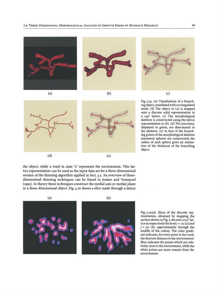
Fig.3.19. (a) Visualization of a branching object, tessellated with a triangulated
mesh. (b) The object in (a) is mapped
onto a discrete solid representation in
a 144 3 lattice. (c) The morphological
skeleton is constructed using the lattice
representation in (b) . (d) The junctions,
displayed in green, are determined in
the skeleton. (e) At four of the branching points of the morphological skeleton
maximum spheres are constructed; the
radius of each sphere gives an estimation of the thickness of the branching
object.
the object, while a voxel in state '0' represents the environment. This lattice representation can be used as the input data set for a three -dimensional
version of the thinning algorithm applied in Sect. 3.3. An overview of threedimensional thinning techniques can be found in Jonker and Vossepoel
(1995). In theory these techniques construct the medial axis or medial plane
in a three-dimensional object. Fig. 3.20 shows a slice made through a lattice
(a)
(b)
Fig.j.zoa.b. Slices of the discrete representation, obtained by mapping the
surface shown in Fig.3.18a onto a 5I2 31attice at respectively the levelj = 151 (a) and
j = 251 (b), approximately through the
middle of the colony. The color grad ient indicates, for every point in the coral,
the shortest distance to the environment.
Blue indicates the points which are relatively close to the environment, while the
white points are more remote from the
environment.
89
(a)
(d)
(b)
(e)
(c)
Fig.3.19. (a) Visualization of a branching object, tessellated with a triangulated
mesh. (b) The object in (a) is mapped
onto a discrete solid representation in
a 144 3 lattice. (c) The morphological
skeleton is constructed using the lattice
representation in (b) . (d) The junctions,
displayed in green, are determined in
the skeleton. (e) At four of the branching points of the morphological skeleton
maximum spheres are constructed; the
radius of each sphere gives an estimation of the thickness of the branching
object.
the object, while a voxel in state '0' represents the environment. This lattice representation can be used as the input data set for a three -dimensional
version of the thinning algorithm applied in Sect. 3.3. An overview of threedimensional thinning techniques can be found in Jonker and Vossepoel
(1995). In theory these techniques construct the medial axis or medial plane
in a three-dimensional object. Fig. 3.20 shows a slice made through a lattice
(a)
(b)
Fig.j.zoa.b. Slices of the discrete representation, obtained by mapping the
surface shown in Fig.3.18a onto a 5I2 31attice at respectively the levelj = 151 (a) and
j = 251 (b), approximately through the
middle of the colony. The color grad ient indicates, for every point in the coral,
the shortest distance to the environment.
Blue indicates the points which are relatively close to the environment, while the
white points are more remote from the
environment.