

90
Fig. 3.21. (a) Constructionof a morphological skeleton in a cylindrical object.
(b) Formationof a newside branch due
to a small perturbation on the surface of
the object
3. MEASURING GROWTH AND FORM
(a)
(b)
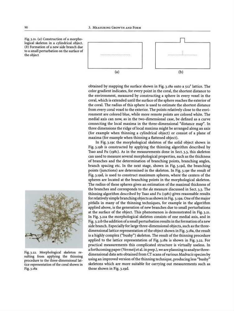
Fig. 3.22. Morphological skeleton resulting from applying the thinning
procedure to the three-dimensionallattice representation of the coralshownin
Fig.3.18a
obtained by mapping the surface shown in Fig.3.18a onto a 512
2 lattice. The
color gradient indicates, for every point in the coral, the shortest distance to
the environment, measured by constructing a sphere in every voxel in the
coral, which is extended until the surface of the sphere reaches the exterior of
the coral. The radius of this sphere is used to estimate the shortest distance
from every coral voxel to the exterior. The points relatively close to the environment are colored blue, while more remote points are colored white. The
medial axis can now, as in the two-dimensional case, be defined as a curve
connecting the local maxima in the three-dimensional "distance map". In
three dimensions the ridge oflocal maxima might be arranged along an axis
(for example when thinning a cylindrical object) or consist of a plane of
maxima (for example when thinning a flattened object).
In Fig. J.l9C the morphological skeleton of the solid object shown in
Fig. J.l9b is constructed by applying the thinning algorithm described by
Tsao and Fu (1981). As in the measurements done in Sect. 3.3, this skeleton
can used to measure several morphological properties, such as the thickness
of branches and the determination of branching points, branching angles,
branch spacing etc. In the next stage, shown in Fig. J.l9d, the branching
points (junctions) are determined in the skeleton. In Fig. J.lge the result of
Fig.3.19d, is used to construct maximum spheres, where the centers of the
spheres are located at the branching points in the morphological skeleton.
The radius of these spheres gives an estimation of the maximal thickness of
the branches and corresponds to the da measure discussed in Sect. 3.3. The
thinning algorithm described by Tsao and Fu (1981) gives reasonable results
for relatively simple branching objects as shown in Fig. 3.19a. One of the major
pitfalls in many of the thinning techniques, for example in the algorithm
applied above, is the generation of new branches due to small perturbations
at the surface of the object. This phenomenon is demonstrated in Fig. 3.21.
In Fig. 3.21a the morphological skeleton consists of one medial axis, and in
Fig.3.21b the addition of a small perturbation results in the formation of a new
side branch. Especially for large three-dimensional objects, such as the threedimensional lattice representation of the object shown in Fig.3.18a, the result
is a highly complex ("bushy") skeleton. The result of the thinning procedure
applied to the lattice representation of Fig.3.18a is shown in Fig. 3.22. For
practical measurements this complicated structure is virtually useless. In
a forthcoming paper (Vermeij et al. in prep.), we are planning to analyze threedimensional data sets obtained from CT scans of various Madracisspecies by
using an improved version of the thinning technique, producing less "bushy"
skeletons which are more suitable for carrying out measurements such as
those shown in Fig. 3.19d.
Fig. 3.21. (a) Constructionof a morphological skeleton in a cylindrical object.
(b) Formationof a newside branch due
to a small perturbation on the surface of
the object
3. MEASURING GROWTH AND FORM
(a)
(b)
Fig. 3.22. Morphological skeleton resulting from applying the thinning
procedure to the three-dimensionallattice representation of the coralshownin
Fig.3.18a
obtained by mapping the surface shown in Fig.3.18a onto a 512
2 lattice. The
color gradient indicates, for every point in the coral, the shortest distance to
the environment, measured by constructing a sphere in every voxel in the
coral, which is extended until the surface of the sphere reaches the exterior of
the coral. The radius of this sphere is used to estimate the shortest distance
from every coral voxel to the exterior. The points relatively close to the environment are colored blue, while more remote points are colored white. The
medial axis can now, as in the two-dimensional case, be defined as a curve
connecting the local maxima in the three-dimensional "distance map". In
three dimensions the ridge oflocal maxima might be arranged along an axis
(for example when thinning a cylindrical object) or consist of a plane of
maxima (for example when thinning a flattened object).
In Fig. J.l9C the morphological skeleton of the solid object shown in
Fig. J.l9b is constructed by applying the thinning algorithm described by
Tsao and Fu (1981). As in the measurements done in Sect. 3.3, this skeleton
can used to measure several morphological properties, such as the thickness
of branches and the determination of branching points, branching angles,
branch spacing etc. In the next stage, shown in Fig. J.l9d, the branching
points (junctions) are determined in the skeleton. In Fig. J.lge the result of
Fig.3.19d, is used to construct maximum spheres, where the centers of the
spheres are located at the branching points in the morphological skeleton.
The radius of these spheres gives an estimation of the maximal thickness of
the branches and corresponds to the da measure discussed in Sect. 3.3. The
thinning algorithm described by Tsao and Fu (1981) gives reasonable results
for relatively simple branching objects as shown in Fig. 3.19a. One of the major
pitfalls in many of the thinning techniques, for example in the algorithm
applied above, is the generation of new branches due to small perturbations
at the surface of the object. This phenomenon is demonstrated in Fig. 3.21.
In Fig. 3.21a the morphological skeleton consists of one medial axis, and in
Fig.3.21b the addition of a small perturbation results in the formation of a new
side branch. Especially for large three-dimensional objects, such as the threedimensional lattice representation of the object shown in Fig.3.18a, the result
is a highly complex ("bushy") skeleton. The result of the thinning procedure
applied to the lattice representation of Fig.3.18a is shown in Fig. 3.22. For
practical measurements this complicated structure is virtually useless. In
a forthcoming paper (Vermeij et al. in prep.), we are planning to analyze threedimensional data sets obtained from CT scans of various Madracisspecies by
using an improved version of the thinning technique, producing less "bushy"
skeletons which are more suitable for carrying out measurements such as
those shown in Fig. 3.19d.