

between large headlands. Relating this research to
smaller estuarine systems involves understanding the
goals of the project, how far offshore the breakwater units
can or should be placed, how long the breakwater units
and how wide the gaps should be, and how much beach
fill is required. Also important is relating the geomorphic
setting of the site to the wave climate. The shore direction
of face, fetch, upland height, and shore configuration are
important site parameters that influence the design
depending on whether a unidirectional or bimodal wave
climate is experienced at the site. Generally, in Chesapeake Bay, the waves are short, and the systems are
scaled down.
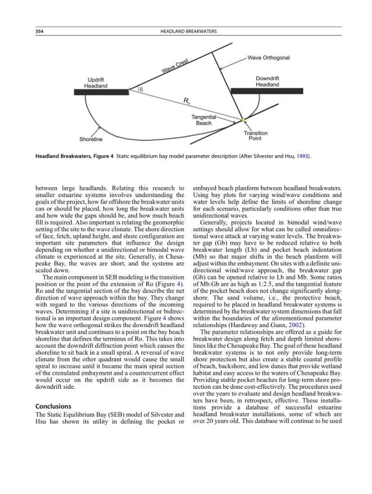
The main component in SEB modeling is the transition
position or the point of the extension of Ro (Figure 4).
Ro and the tangential section of the bay describe the net
direction of wave approach within the bay. They change
with regard to the various directions of the incoming
waves. Determining if a site is unidirectional or bidirectional is an important design component. Figure 4 shows
how the wave orthogonal strikes the downdrift headland
breakwater unit and continues to a point on the bay beach
shoreline that defines the terminus of Ro. This takes into
account the downdrift diffraction point which causes the
shoreline to sit back in a small spiral. A reversal of wave
climate from the other quadrant would cause the small
spiral to increase until it became the main spiral section
of the crenulated embayment and a countercurrent effect
would occur on the updrift side as it becomes the
downdrift side.
Conclusions
The Static Equilibrium Bay (SEB) model of Silvester and
Hsu has shown its utility in defining the pocket or
embayed beach planform between headland breakwaters.
Using bay plots for varying wind/wave conditions and
water levels help define the limits of shoreline change
for each scenario, particularly conditions other than true
unidirectional waves.
Generally, projects located in bimodal wind/wave
settings should allow for what can be called omnidirectional wave attack at varying water levels. The breakwater gap (Gb) may have to be reduced relative to both
breakwater length (Lb) and pocket beach indentation
(Mb) so that major shifts in the beach planform will
adjust within the embayment. On sites with a definite unidirectional wind/wave approach, the breakwater gap
(Gb) can be opened relative to Lb and Mb. Some ratios
of Mb:Gb are as high as 1:2.5, and the tangential feature
of the pocket beach does not change significantly alongshore. The sand volume, i.e., the protective beach,
required to be placed in headland breakwater systems is
determined by the breakwater system dimensions that fall
within the boundaries of the aforementioned parameter
relationships (Hardaway and Gunn, 2002).
The parameter relationships are offered as a guide for
breakwater design along fetch and depth limited shorelines like the Chesapeake Bay. The goal of these headland
breakwater systems is to not only provide long-term
shore protection but also create a stable coastal profile
of beach, backshore, and low dunes that provide wetland
habitat and easy access to the waters of Chesapeake Bay.
Providing stable pocket beaches for long-term shore protection can be done cost-effectively. The procedures used
over the years to evaluate and design headland breakwaters have been, in retrospect, effective. These installations provide a database of successful estuarine
headland breakwater installations, some of which are
over 20 years old. This database will continue to be used
Headland Breakwaters, Figure 4 Static equilibrium bay model parameter description (After Silvester and Hsu, 1993).
354
HEADLAND BREAKWATERS
smaller estuarine systems involves understanding the
goals of the project, how far offshore the breakwater units
can or should be placed, how long the breakwater units
and how wide the gaps should be, and how much beach
fill is required. Also important is relating the geomorphic
setting of the site to the wave climate. The shore direction
of face, fetch, upland height, and shore configuration are
important site parameters that influence the design
depending on whether a unidirectional or bimodal wave
climate is experienced at the site. Generally, in Chesapeake Bay, the waves are short, and the systems are
scaled down.
The main component in SEB modeling is the transition
position or the point of the extension of Ro (Figure 4).
Ro and the tangential section of the bay describe the net
direction of wave approach within the bay. They change
with regard to the various directions of the incoming
waves. Determining if a site is unidirectional or bidirectional is an important design component. Figure 4 shows
how the wave orthogonal strikes the downdrift headland
breakwater unit and continues to a point on the bay beach
shoreline that defines the terminus of Ro. This takes into
account the downdrift diffraction point which causes the
shoreline to sit back in a small spiral. A reversal of wave
climate from the other quadrant would cause the small
spiral to increase until it became the main spiral section
of the crenulated embayment and a countercurrent effect
would occur on the updrift side as it becomes the
downdrift side.
Conclusions
The Static Equilibrium Bay (SEB) model of Silvester and
Hsu has shown its utility in defining the pocket or
embayed beach planform between headland breakwaters.
Using bay plots for varying wind/wave conditions and
water levels help define the limits of shoreline change
for each scenario, particularly conditions other than true
unidirectional waves.
Generally, projects located in bimodal wind/wave
settings should allow for what can be called omnidirectional wave attack at varying water levels. The breakwater gap (Gb) may have to be reduced relative to both
breakwater length (Lb) and pocket beach indentation
(Mb) so that major shifts in the beach planform will
adjust within the embayment. On sites with a definite unidirectional wind/wave approach, the breakwater gap
(Gb) can be opened relative to Lb and Mb. Some ratios
of Mb:Gb are as high as 1:2.5, and the tangential feature
of the pocket beach does not change significantly alongshore. The sand volume, i.e., the protective beach,
required to be placed in headland breakwater systems is
determined by the breakwater system dimensions that fall
within the boundaries of the aforementioned parameter
relationships (Hardaway and Gunn, 2002).
The parameter relationships are offered as a guide for
breakwater design along fetch and depth limited shorelines like the Chesapeake Bay. The goal of these headland
breakwater systems is to not only provide long-term
shore protection but also create a stable coastal profile
of beach, backshore, and low dunes that provide wetland
habitat and easy access to the waters of Chesapeake Bay.
Providing stable pocket beaches for long-term shore protection can be done cost-effectively. The procedures used
over the years to evaluate and design headland breakwaters have been, in retrospect, effective. These installations provide a database of successful estuarine
headland breakwater installations, some of which are
over 20 years old. This database will continue to be used
Headland Breakwaters, Figure 4 Static equilibrium bay model parameter description (After Silvester and Hsu, 1993).
354
HEADLAND BREAKWATERS