

Novel Bioreactors for Culturing Marine Organisms 12.8 High-Temperature and/or High-Pressure Bioreactors (HP-/HTBR) 377
Part B | 12.8
Pressure
module
Vent
Vent
Vent
OT
Culture
sample
Hydrostatic bioreactor
Oven
OT
RG
RG
RG
He
CO 2 + H 2
CO 2 + H 2
Gas
P
OT
P
Two-way valve
Three-way valve
Check valve
Pressure gauge
Safety head
TC
SSR
P
Harvest
Hyperbaric
bioreactor
Culture
sample
Gas
recycle
CA
CA
Diaphragm compressor
Heat belt
Growth
medium
N 2
Liquid
pump
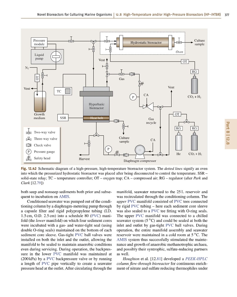
Fig. 12.42 Schematic diagram of a high-pressure, high-temperature bioreactor system. The dotted lines signify an oven
into which the pressurized hydrostatic bioreactor was placed after being disconnected to control the temperature. SSR –
solid-state relay; TC – temperature controller; OT – oxygen trap; CA – compressed air; RG – regulator (after Park and
Clark [12.79])
both seep and nonseep sediments both prior and subsequent to incubation on AMIS.
Conditioned seawater was pumped out of the conditioning column by a diaphragm-metering pump through
a capsule filter and rigid polypropylene tubing (I.D.
1:5 cm, O.D. 2:5 cm) into a schedule 80 (PVC) manifold (the lower manifold) on which four sediment cores
were incubated with a gas- and water-tight seal (using
double O-ring seals) maintained on the bottom of each
sediment core sleeve. Gas-tight PVC ball valves were
installed on both the inlet and the outlet, allowing the
manifold to be sealed to maintain anaerobic conditions
even during servicing. During operation, the backpressure in the lower PVC manifold was maintained at
(200 kPa) by a PVC backpressure valve or by running
a length of PVC pipe vertically to create a seawater
pressure head at the outlet. After circulating through the
manifold, seawater returned to the 25 L reservoir and
was recirculated through the conditioning column. The
upper PVC manifold consisted of PVC tees connected
by rigid PVC tubing – here each sediment core sleeve
was also sealed to a PVC tee fitting with O-ring seals.
The upper PVC manifold was connected to a chilled
seawater system (5
ı C) and could be sealed at both the
inlet and outlet by gas-tight PVC ball valves. During
operation, the entire manifold assembly and seawater
reservoir were maintained in a cold room at 5
ı C. The
AMIS system thus successfully stimulated the maintenance and growth of anaerobic methanotrophic archaea,
and possibly their syntrophic, sulfate-reducing partners
as well.
Houghton et al. [12.81] developed a PEEK-HPLC
column flow-through bioreactor for continuous enrichment of nitrate and sulfate reducing thermophiles under
Part B | 12.8
Pressure
module
Vent
Vent
Vent
OT
Culture
sample
Hydrostatic bioreactor
Oven
OT
RG
RG
RG
He
CO 2 + H 2
CO 2 + H 2
Gas
P
OT
P
Two-way valve
Three-way valve
Check valve
Pressure gauge
Safety head
TC
SSR
P
Harvest
Hyperbaric
bioreactor
Culture
sample
Gas
recycle
CA
CA
Diaphragm compressor
Heat belt
Growth
medium
N 2
Liquid
pump
Fig. 12.42 Schematic diagram of a high-pressure, high-temperature bioreactor system. The dotted lines signify an oven
into which the pressurized hydrostatic bioreactor was placed after being disconnected to control the temperature. SSR –
solid-state relay; TC – temperature controller; OT – oxygen trap; CA – compressed air; RG – regulator (after Park and
Clark [12.79])
both seep and nonseep sediments both prior and subsequent to incubation on AMIS.
Conditioned seawater was pumped out of the conditioning column by a diaphragm-metering pump through
a capsule filter and rigid polypropylene tubing (I.D.
1:5 cm, O.D. 2:5 cm) into a schedule 80 (PVC) manifold (the lower manifold) on which four sediment cores
were incubated with a gas- and water-tight seal (using
double O-ring seals) maintained on the bottom of each
sediment core sleeve. Gas-tight PVC ball valves were
installed on both the inlet and the outlet, allowing the
manifold to be sealed to maintain anaerobic conditions
even during servicing. During operation, the backpressure in the lower PVC manifold was maintained at
(200 kPa) by a PVC backpressure valve or by running
a length of PVC pipe vertically to create a seawater
pressure head at the outlet. After circulating through the
manifold, seawater returned to the 25 L reservoir and
was recirculated through the conditioning column. The
upper PVC manifold consisted of PVC tees connected
by rigid PVC tubing – here each sediment core sleeve
was also sealed to a PVC tee fitting with O-ring seals.
The upper PVC manifold was connected to a chilled
seawater system (5
ı C) and could be sealed at both the
inlet and outlet by gas-tight PVC ball valves. During
operation, the entire manifold assembly and seawater
reservoir were maintained in a cold room at 5
ı C. The
AMIS system thus successfully stimulated the maintenance and growth of anaerobic methanotrophic archaea,
and possibly their syntrophic, sulfate-reducing partners
as well.
Houghton et al. [12.81] developed a PEEK-HPLC
column flow-through bioreactor for continuous enrichment of nitrate and sulfate reducing thermophiles under