

Part B | 12.8
376 Part B Tools and Methods in Marine Biotechnology
ATM
VAC
O
P
T
GR
S
ATM
PT
DV
IP
P
PG
TC
V
DV
P
VP
PC
OT
He
F
ATM
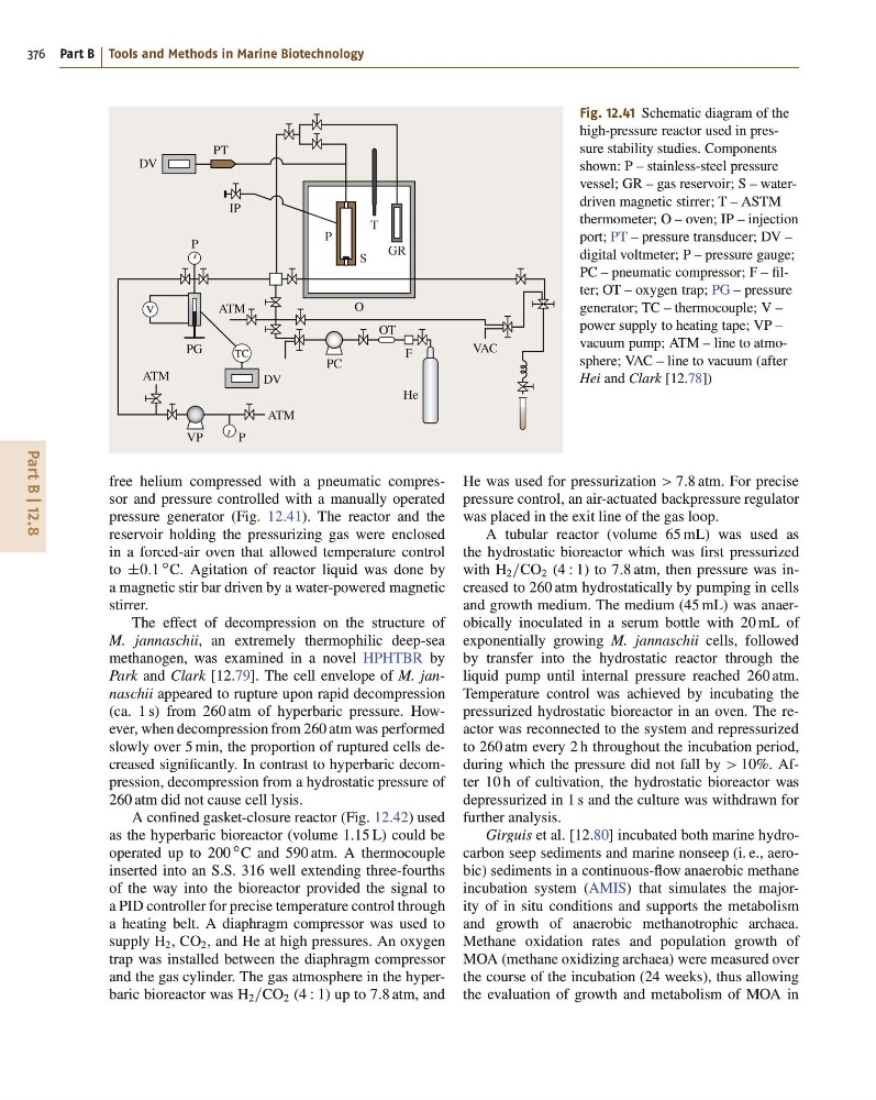
Fig. 12.41 Schematic diagram of the
high-pressure reactor used in pressure stability studies. Components
shown: P – stainless-steel pressure
vessel; GR – gas reservoir; S – waterdriven magnetic stirrer; T – ASTM
thermometer; O – oven; IP – injection
port; PT – pressure transducer; DV –
digital voltmeter; P – pressure gauge;
PC – pneumatic compressor; F – filter; OT – oxygen trap; PG – pressure
generator; TC – thermocouple; V –
power supply to heating tape; VP –
vacuum pump; ATM – line to atmosphere; VAC – line to vacuum (after
Hei and Clark [12.78])
free helium compressed with a pneumatic compressor and pressure controlled with a manually operated
pressure generator (Fig. 12.41). The reactor and the
reservoir holding the pressurizing gas were enclosed
in a forced-air oven that allowed temperature control
to ˙0:1
ı C. Agitation of reactor liquid was done by
a magnetic stir bar driven by a water-powered magnetic
stirrer.
The effect of decompression on the structure of
M. jannaschii, an extremely thermophilic deep-sea
methanogen, was examined in a novel HPHTBR by
Park and Clark [12.79]. The cell envelope of M. jannaschii appeared to rupture upon rapid decompression
(ca. 1 s) from 260 atm of hyperbaric pressure. However, when decompression from 260 atm was performed
slowly over 5 min, the proportion of ruptured cells decreased significantly. In contrast to hyperbaric decompression, decompression from a hydrostatic pressure of
260 atm did not cause cell lysis.
A confined gasket-closure reactor (Fig. 12.42) used
as the hyperbaric bioreactor (volume 1:15 L) could be
operated up to 200
ı C and 590 atm. A thermocouple
inserted into an S.S. 316 well extending three-fourths
of the way into the bioreactor provided the signal to
a PID controller for precise temperature control through
a heating belt. A diaphragm compressor was used to
supply H 2 , CO 2 , and He at high pressures. An oxygen
trap was installed between the diaphragm compressor
and the gas cylinder. The gas atmosphere in the hyperbaric bioreactor was H 2 =CO 2 (4 W 1) up to 7:8 atm, and
He was used for pressurization > 7:8 atm. For precise
pressure control, an air-actuated backpressure regulator
was placed in the exit line of the gas loop.
A tubular reactor (volume 65 mL) was used as
the hydrostatic bioreactor which was first pressurized
with H 2 =CO 2 (4 W 1) to 7:8 atm, then pressure was increased to 260 atm hydrostatically by pumping in cells
and growth medium. The medium (45 mL) was anaerobically inoculated in a serum bottle with 20 mL of
exponentially growing M. jannaschii cells, followed
by transfer into the hydrostatic reactor through the
liquid pump until internal pressure reached 260 atm.
Temperature control was achieved by incubating the
pressurized hydrostatic bioreactor in an oven. The reactor was reconnected to the system and repressurized
to 260 atm every 2 h throughout the incubation period,
during which the pressure did not fall by > 10%. After 10 h of cultivation, the hydrostatic bioreactor was
depressurized in 1 s and the culture was withdrawn for
further analysis.
Girguis et al. [12.80] incubated both marine hydrocarbon seep sediments and marine nonseep (i. e., aerobic) sediments in a continuous-flow anaerobic methane
incubation system (AMIS) that simulates the majority of in situ conditions and supports the metabolism
and growth of anaerobic methanotrophic archaea.
Methane oxidation rates and population growth of
MOA (methane oxidizing archaea) were measured over
the course of the incubation (24 weeks), thus allowing
the evaluation of growth and metabolism of MOA in
376 Part B Tools and Methods in Marine Biotechnology
ATM
VAC
O
P
T
GR
S
ATM
PT
DV
IP
P
PG
TC
V
DV
P
VP
PC
OT
He
F
ATM
Fig. 12.41 Schematic diagram of the
high-pressure reactor used in pressure stability studies. Components
shown: P – stainless-steel pressure
vessel; GR – gas reservoir; S – waterdriven magnetic stirrer; T – ASTM
thermometer; O – oven; IP – injection
port; PT – pressure transducer; DV –
digital voltmeter; P – pressure gauge;
PC – pneumatic compressor; F – filter; OT – oxygen trap; PG – pressure
generator; TC – thermocouple; V –
power supply to heating tape; VP –
vacuum pump; ATM – line to atmosphere; VAC – line to vacuum (after
Hei and Clark [12.78])
free helium compressed with a pneumatic compressor and pressure controlled with a manually operated
pressure generator (Fig. 12.41). The reactor and the
reservoir holding the pressurizing gas were enclosed
in a forced-air oven that allowed temperature control
to ˙0:1
ı C. Agitation of reactor liquid was done by
a magnetic stir bar driven by a water-powered magnetic
stirrer.
The effect of decompression on the structure of
M. jannaschii, an extremely thermophilic deep-sea
methanogen, was examined in a novel HPHTBR by
Park and Clark [12.79]. The cell envelope of M. jannaschii appeared to rupture upon rapid decompression
(ca. 1 s) from 260 atm of hyperbaric pressure. However, when decompression from 260 atm was performed
slowly over 5 min, the proportion of ruptured cells decreased significantly. In contrast to hyperbaric decompression, decompression from a hydrostatic pressure of
260 atm did not cause cell lysis.
A confined gasket-closure reactor (Fig. 12.42) used
as the hyperbaric bioreactor (volume 1:15 L) could be
operated up to 200
ı C and 590 atm. A thermocouple
inserted into an S.S. 316 well extending three-fourths
of the way into the bioreactor provided the signal to
a PID controller for precise temperature control through
a heating belt. A diaphragm compressor was used to
supply H 2 , CO 2 , and He at high pressures. An oxygen
trap was installed between the diaphragm compressor
and the gas cylinder. The gas atmosphere in the hyperbaric bioreactor was H 2 =CO 2 (4 W 1) up to 7:8 atm, and
He was used for pressurization > 7:8 atm. For precise
pressure control, an air-actuated backpressure regulator
was placed in the exit line of the gas loop.
A tubular reactor (volume 65 mL) was used as
the hydrostatic bioreactor which was first pressurized
with H 2 =CO 2 (4 W 1) to 7:8 atm, then pressure was increased to 260 atm hydrostatically by pumping in cells
and growth medium. The medium (45 mL) was anaerobically inoculated in a serum bottle with 20 mL of
exponentially growing M. jannaschii cells, followed
by transfer into the hydrostatic reactor through the
liquid pump until internal pressure reached 260 atm.
Temperature control was achieved by incubating the
pressurized hydrostatic bioreactor in an oven. The reactor was reconnected to the system and repressurized
to 260 atm every 2 h throughout the incubation period,
during which the pressure did not fall by > 10%. After 10 h of cultivation, the hydrostatic bioreactor was
depressurized in 1 s and the culture was withdrawn for
further analysis.
Girguis et al. [12.80] incubated both marine hydrocarbon seep sediments and marine nonseep (i. e., aerobic) sediments in a continuous-flow anaerobic methane
incubation system (AMIS) that simulates the majority of in situ conditions and supports the metabolism
and growth of anaerobic methanotrophic archaea.
Methane oxidation rates and population growth of
MOA (methane oxidizing archaea) were measured over
the course of the incubation (24 weeks), thus allowing
the evaluation of growth and metabolism of MOA in