

Novel Bioreactors for Culturing Marine Organisms 12.8 High-Temperature and/or High-Pressure Bioreactors (HP-/HTBR) 375
Part B | 12.8
Integrator/pneumatics
GC and
NaOH scrub
Ballast
Vacuum pump
Pressure transducer
M
CV
CV
P
Gas
compressor
Vent to fume hood
Liquid sample system
Liquid compressor/
vent to fume hood
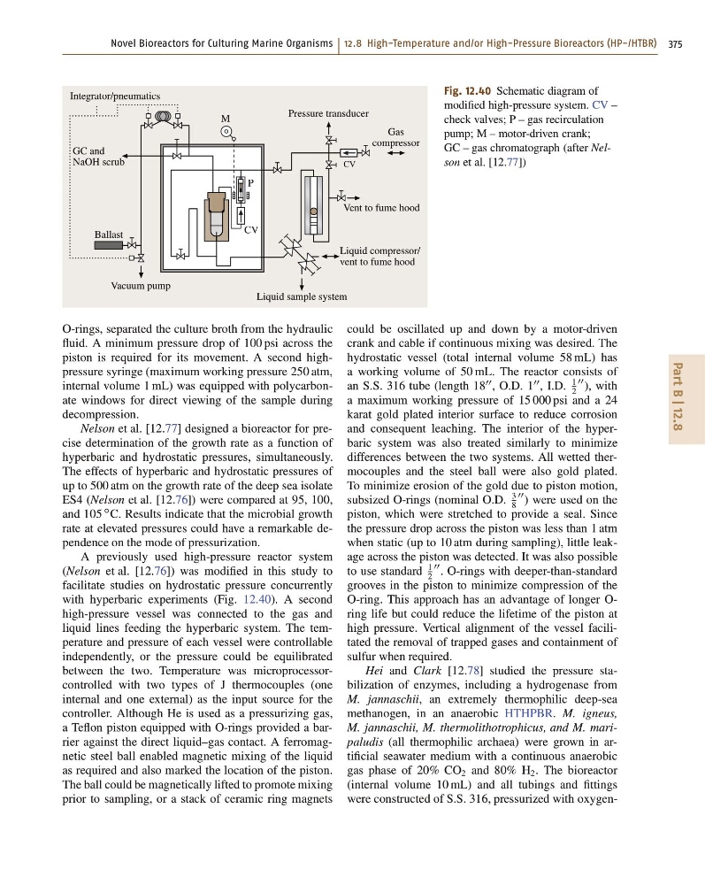
Fig. 12.40 Schematic diagram of
modified high-pressure system. CV –
check valves; P – gas recirculation
pump; M – motor-driven crank;
GC – gas chromatograph (after Nelson et al. [12.77])
O-rings, separated the culture broth from the hydraulic
fluid. A minimum pressure drop of 100 psi across the
piston is required for its movement. A second highpressure syringe (maximum working pressure 250 atm,
internal volume 1 mL) was equipped with polycarbonate windows for direct viewing of the sample during
decompression.
Nelson et al. [12.77] designed a bioreactor for precise determination of the growth rate as a function of
hyperbaric and hydrostatic pressures, simultaneously.
The effects of hyperbaric and hydrostatic pressures of
up to 500 atm on the growth rate of the deep sea isolate
ES4 (Nelson et al. [12.76]) were compared at 95, 100,
and 105
ı C. Results indicate that the microbial growth
rate at elevated pressures could have a remarkable dependence on the mode of pressurization.
A previously used high-pressure reactor system
(Nelson et al. [12.76]) was modified in this study to
facilitate studies on hydrostatic pressure concurrently
with hyperbaric experiments (Fig. 12.40). A second
high-pressure vessel was connected to the gas and
liquid lines feeding the hyperbaric system. The temperature and pressure of each vessel were controllable
independently, or the pressure could be equilibrated
between the two. Temperature was microprocessorcontrolled with two types of J thermocouples (one
internal and one external) as the input source for the
controller. Although He is used as a pressurizing gas,
a Teflon piston equipped with O-rings provided a barrier against the direct liquid–gas contact. A ferromagnetic steel ball enabled magnetic mixing of the liquid
as required and also marked the location of the piston.
The ball could be magnetically lifted to promote mixing
prior to sampling, or a stack of ceramic ring magnets
could be oscillated up and down by a motor-driven
crank and cable if continuous mixing was desired. The
hydrostatic vessel (total internal volume 58 mL) has
a working volume of 50 mL. The reactor consists of
an S.S. 316 tube (length 18
00 , O.D. 1
00 , I.D.
1
2
00 ), with
a maximum working pressure of 15 000 psi and a 24
karat gold plated interior surface to reduce corrosion
and consequent leaching. The interior of the hyperbaric system was also treated similarly to minimize
differences between the two systems. All wetted thermocouples and the steel ball were also gold plated.
To minimize erosion of the gold due to piston motion,
subsized O-rings (nominal O.D.
3
8
00 ) were used on the
piston, which were stretched to provide a seal. Since
the pressure drop across the piston was less than 1 atm
when static (up to 10 atm during sampling), little leakage across the piston was detected. It was also possible
to use standard
1
2
00 . O-rings with deeper-than-standard
grooves in the piston to minimize compression of the
O-ring. This approach has an advantage of longer Oring life but could reduce the lifetime of the piston at
high pressure. Vertical alignment of the vessel facilitated the removal of trapped gases and containment of
sulfur when required.
Hei and Clark [12.78] studied the pressure stabilization of enzymes, including a hydrogenase from
M. jannaschii, an extremely thermophilic deep-sea
methanogen, in an anaerobic HTHPBR. M. igneus,
M. jannaschii, M. thermolithotrophicus, and M. maripaludis (all thermophilic archaea) were grown in artificial seawater medium with a continuous anaerobic
gas phase of 20% CO 2 and 80% H 2 . The bioreactor
(internal volume 10 mL) and all tubings and fittings
were constructed of S.S. 316, pressurized with oxygen-
Part B | 12.8
Integrator/pneumatics
GC and
NaOH scrub
Ballast
Vacuum pump
Pressure transducer
M
CV
CV
P
Gas
compressor
Vent to fume hood
Liquid sample system
Liquid compressor/
vent to fume hood
Fig. 12.40 Schematic diagram of
modified high-pressure system. CV –
check valves; P – gas recirculation
pump; M – motor-driven crank;
GC – gas chromatograph (after Nelson et al. [12.77])
O-rings, separated the culture broth from the hydraulic
fluid. A minimum pressure drop of 100 psi across the
piston is required for its movement. A second highpressure syringe (maximum working pressure 250 atm,
internal volume 1 mL) was equipped with polycarbonate windows for direct viewing of the sample during
decompression.
Nelson et al. [12.77] designed a bioreactor for precise determination of the growth rate as a function of
hyperbaric and hydrostatic pressures, simultaneously.
The effects of hyperbaric and hydrostatic pressures of
up to 500 atm on the growth rate of the deep sea isolate
ES4 (Nelson et al. [12.76]) were compared at 95, 100,
and 105
ı C. Results indicate that the microbial growth
rate at elevated pressures could have a remarkable dependence on the mode of pressurization.
A previously used high-pressure reactor system
(Nelson et al. [12.76]) was modified in this study to
facilitate studies on hydrostatic pressure concurrently
with hyperbaric experiments (Fig. 12.40). A second
high-pressure vessel was connected to the gas and
liquid lines feeding the hyperbaric system. The temperature and pressure of each vessel were controllable
independently, or the pressure could be equilibrated
between the two. Temperature was microprocessorcontrolled with two types of J thermocouples (one
internal and one external) as the input source for the
controller. Although He is used as a pressurizing gas,
a Teflon piston equipped with O-rings provided a barrier against the direct liquid–gas contact. A ferromagnetic steel ball enabled magnetic mixing of the liquid
as required and also marked the location of the piston.
The ball could be magnetically lifted to promote mixing
prior to sampling, or a stack of ceramic ring magnets
could be oscillated up and down by a motor-driven
crank and cable if continuous mixing was desired. The
hydrostatic vessel (total internal volume 58 mL) has
a working volume of 50 mL. The reactor consists of
an S.S. 316 tube (length 18
00 , O.D. 1
00 , I.D.
1
2
00 ), with
a maximum working pressure of 15 000 psi and a 24
karat gold plated interior surface to reduce corrosion
and consequent leaching. The interior of the hyperbaric system was also treated similarly to minimize
differences between the two systems. All wetted thermocouples and the steel ball were also gold plated.
To minimize erosion of the gold due to piston motion,
subsized O-rings (nominal O.D.
3
8
00 ) were used on the
piston, which were stretched to provide a seal. Since
the pressure drop across the piston was less than 1 atm
when static (up to 10 atm during sampling), little leakage across the piston was detected. It was also possible
to use standard
1
2
00 . O-rings with deeper-than-standard
grooves in the piston to minimize compression of the
O-ring. This approach has an advantage of longer Oring life but could reduce the lifetime of the piston at
high pressure. Vertical alignment of the vessel facilitated the removal of trapped gases and containment of
sulfur when required.
Hei and Clark [12.78] studied the pressure stabilization of enzymes, including a hydrogenase from
M. jannaschii, an extremely thermophilic deep-sea
methanogen, in an anaerobic HTHPBR. M. igneus,
M. jannaschii, M. thermolithotrophicus, and M. maripaludis (all thermophilic archaea) were grown in artificial seawater medium with a continuous anaerobic
gas phase of 20% CO 2 and 80% H 2 . The bioreactor
(internal volume 10 mL) and all tubings and fittings
were constructed of S.S. 316, pressurized with oxygen-