

Part B | 12.8
374 Part B Tools and Methods in Marine Biotechnology
reaction vessel and a magnetically driven pump to recirculate gas through the liquid phase. A fiber optic
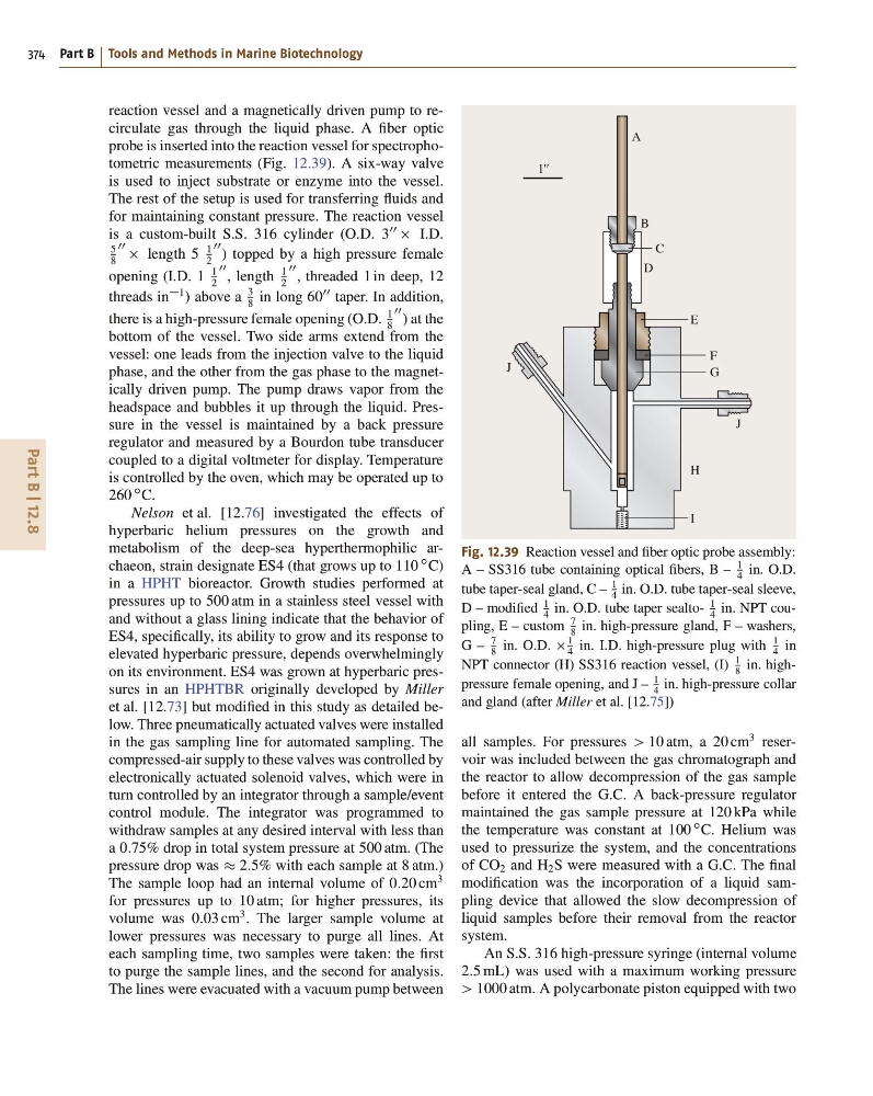
probe is inserted into the reaction vessel for spectrophotometric measurements (Fig. 12.39). A six-way valve
is used to inject substrate or enzyme into the vessel.
The rest of the setup is used for transferring fluids and
for maintaining constant pressure. The reaction vessel
is a custom-built S.S. 316 cylinder (O.D. 3
00
I.D.
5
8
00 length 5
1
2
00 ) topped by a high pressure female
opening (I.D. 1
1
2
00 , length
1
2
00 , threaded 1 in deep, 12
threads in
1 ) above a
3
8
in long 60
00 taper. In addition,
there is a high-pressure female opening (O.D.
1
8
00 ) at the
bottom of the vessel. Two side arms extend from the
vessel: one leads from the injection valve to the liquid
phase, and the other from the gas phase to the magnetically driven pump. The pump draws vapor from the
headspace and bubbles it up through the liquid. Pressure in the vessel is maintained by a back pressure
regulator and measured by a Bourdon tube transducer
coupled to a digital voltmeter for display. Temperature
is controlled by the oven, which may be operated up to
260
ı C.
Nelson et al. [12.76] investigated the effects of
hyperbaric helium pressures on the growth and
metabolism of the deep-sea hyperthermophilic archaeon, strain designate ES4 (that grows up to 110
ı C)
in a HPHT bioreactor. Growth studies performed at
pressures up to 500 atm in a stainless steel vessel with
and without a glass lining indicate that the behavior of
ES4, specifically, its ability to grow and its response to
elevated hyperbaric pressure, depends overwhelmingly
on its environment. ES4 was grown at hyperbaric pressures in an HPHTBR originally developed by Miller
et al. [12.73] but modified in this study as detailed below. Three pneumatically actuated valves were installed
in the gas sampling line for automated sampling. The
compressed-air supply to these valves was controlled by
electronically actuated solenoid valves, which were in
turn controlled by an integrator through a sample/event
control module. The integrator was programmed to
withdraw samples at any desired interval with less than
a 0:75% drop in total system pressure at 500 atm. (The
pressure drop was 2:5% with each sample at 8 atm.)
The sample loop had an internal volume of 0:20 cm
3
for pressures up to 10 atm; for higher pressures, its
volume was 0:03 cm
3 . The larger sample volume at
lower pressures was necessary to purge all lines. At
each sampling time, two samples were taken: the first
to purge the sample lines, and the second for analysis.
The lines were evacuated with a vacuum pump between
1''
J
J
A
B
C
D
E
F
G
H
I
Fig. 12.39 Reaction vessel and fiber optic probe assembly:
A – SS316 tube containing optical fibers, B –
1
4 in. O.D.
tube taper-seal gland, C –
1
4 in. O.D. tube taper-seal sleeve,
D – modified
1
4
in. O.D. tube taper sealto1
4
in. NPT coupling, E – custom
7
8
in. high-pressure gland, F – washers,
G –
7
8 in. O.D.
1
4 in. I.D. high-pressure plug with
1
4 in
NPT connector (H) SS316 reaction vessel, (I)
1
8
in. highpressure female opening, and J –
1
4
in. high-pressure collar
and gland (after Miller et al. [12.75])
all samples. For pressures > 10 atm, a 20 cm
3 reservoir was included between the gas chromatograph and
the reactor to allow decompression of the gas sample
before it entered the G.C. A back-pressure regulator
maintained the gas sample pressure at 120 kPa while
the temperature was constant at 100
ı C. Helium was
used to pressurize the system, and the concentrations
of CO 2 and H 2 S were measured with a G.C. The final
modification was the incorporation of a liquid sampling device that allowed the slow decompression of
liquid samples before their removal from the reactor
system.
An S.S. 316 high-pressure syringe (internal volume
2:5 mL) was used with a maximum working pressure
> 1000 atm. A polycarbonate piston equipped with two
374 Part B Tools and Methods in Marine Biotechnology
reaction vessel and a magnetically driven pump to recirculate gas through the liquid phase. A fiber optic
probe is inserted into the reaction vessel for spectrophotometric measurements (Fig. 12.39). A six-way valve
is used to inject substrate or enzyme into the vessel.
The rest of the setup is used for transferring fluids and
for maintaining constant pressure. The reaction vessel
is a custom-built S.S. 316 cylinder (O.D. 3
00
I.D.
5
8
00 length 5
1
2
00 ) topped by a high pressure female
opening (I.D. 1
1
2
00 , length
1
2
00 , threaded 1 in deep, 12
threads in
1 ) above a
3
8
in long 60
00 taper. In addition,
there is a high-pressure female opening (O.D.
1
8
00 ) at the
bottom of the vessel. Two side arms extend from the
vessel: one leads from the injection valve to the liquid
phase, and the other from the gas phase to the magnetically driven pump. The pump draws vapor from the
headspace and bubbles it up through the liquid. Pressure in the vessel is maintained by a back pressure
regulator and measured by a Bourdon tube transducer
coupled to a digital voltmeter for display. Temperature
is controlled by the oven, which may be operated up to
260
ı C.
Nelson et al. [12.76] investigated the effects of
hyperbaric helium pressures on the growth and
metabolism of the deep-sea hyperthermophilic archaeon, strain designate ES4 (that grows up to 110
ı C)
in a HPHT bioreactor. Growth studies performed at
pressures up to 500 atm in a stainless steel vessel with
and without a glass lining indicate that the behavior of
ES4, specifically, its ability to grow and its response to
elevated hyperbaric pressure, depends overwhelmingly
on its environment. ES4 was grown at hyperbaric pressures in an HPHTBR originally developed by Miller
et al. [12.73] but modified in this study as detailed below. Three pneumatically actuated valves were installed
in the gas sampling line for automated sampling. The
compressed-air supply to these valves was controlled by
electronically actuated solenoid valves, which were in
turn controlled by an integrator through a sample/event
control module. The integrator was programmed to
withdraw samples at any desired interval with less than
a 0:75% drop in total system pressure at 500 atm. (The
pressure drop was 2:5% with each sample at 8 atm.)
The sample loop had an internal volume of 0:20 cm
3
for pressures up to 10 atm; for higher pressures, its
volume was 0:03 cm
3 . The larger sample volume at
lower pressures was necessary to purge all lines. At
each sampling time, two samples were taken: the first
to purge the sample lines, and the second for analysis.
The lines were evacuated with a vacuum pump between
1''
J
J
A
B
C
D
E
F
G
H
I
Fig. 12.39 Reaction vessel and fiber optic probe assembly:
A – SS316 tube containing optical fibers, B –
1
4 in. O.D.
tube taper-seal gland, C –
1
4 in. O.D. tube taper-seal sleeve,
D – modified
1
4
in. O.D. tube taper sealto1
4
in. NPT coupling, E – custom
7
8
in. high-pressure gland, F – washers,
G –
7
8 in. O.D.
1
4 in. I.D. high-pressure plug with
1
4 in
NPT connector (H) SS316 reaction vessel, (I)
1
8
in. highpressure female opening, and J –
1
4
in. high-pressure collar
and gland (after Miller et al. [12.75])
all samples. For pressures > 10 atm, a 20 cm
3 reservoir was included between the gas chromatograph and
the reactor to allow decompression of the gas sample
before it entered the G.C. A back-pressure regulator
maintained the gas sample pressure at 120 kPa while
the temperature was constant at 100
ı C. Helium was
used to pressurize the system, and the concentrations
of CO 2 and H 2 S were measured with a G.C. The final
modification was the incorporation of a liquid sampling device that allowed the slow decompression of
liquid samples before their removal from the reactor
system.
An S.S. 316 high-pressure syringe (internal volume
2:5 mL) was used with a maximum working pressure
> 1000 atm. A polycarbonate piston equipped with two