

Novel Bioreactors for Culturing Marine Organisms 12.7 Fluidized Bed and Moving Bed Bioreactors (FBBR and MBBR) 365
Part B | 12.7
ward fluidization, the active volume is low and fluidization performance may deteriorate over time and may
not remain at the optimum level, primarily due to the
changing density of the carriers with biofilm growth on
their surfaces. An effective alternative to an FBBR is
an MBBR (Table 12.8), which has carrier particles that
are continuously in motion. As the liquid circulates, the
carriers move through the liquid between two retention
grids at two ends of the reactor and are agitated either
mechanically or hydrodynamically by liquid jets. High
shear stress from water circulation coupled with interparticle collision prevents uncontrolled proliferation of
biofilm on the carrier surface and thereby stabilizes the
reactor system.
An MBBR is thus self-cleaning and has low head
loss. In fact, MBBRs with up to 60% of the working
volume occupied by carriers have been used and found
to perform satisfactorily.
A pilot scale, submerged MBBR was installed at
the Montreal Biodome (a 3:25 million closed-circuit
mesocosm) to deal with the constraints of seawater denitrification by an attached-growth process, with an aim
to optimize a large-scale MBBR. Labelle et al. [12.66],
evaluated the seawater treatment performance of the
reactors, using methanol as carbon source at different C=N ratios and examined its efficiency in preventing sulfate reduction by limiting biofilm thickness, dead mixing zones and residual substrate in the
outflow.
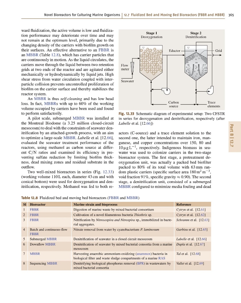
Two well-mixed bioreactors in series (Fig. 12.33)
(working volume 110 L each, diameter 43 cm and with
conical bottom) were used for deoxygenation and denitrification, respectively. Methanol was fed to both reTable 12.8 Fluidized bed and moving bed bioreactors (FBBR and MBBR)
Sl Bioreactor
Marine strain and bioprocess
Reference
1 FBBR
Digestion of marine waste by mixed bacterial consortium
Cytryn et al. [12.61]
2 FBBR
Cultivation of a novel filamentous bacteria Thiothrix sp.
Cytryn et al. [12.62]
3 FBBR
Nitrification by Nitrosospira and Nitrospira sp., immobilized in bacterial aggregates.
Schramm et al. [12.63]
4 Batch and continuous-flow
FBBR
Nitrate removal from water by cyanobacterium P. laminosum
Garbisu et al. [12.65]
5 Submerged MBBR
Denitrification of seawater in a closed circuit mesocosm
Labelle et al. [12.66]
6 Downflow MBBR
Denitrification of seawater by mixed bacterial consortia from a marine
mesocosm
Dupla et al. [12.67]
7 MBBR
Harvesting anaerobic ammonium-oxidizing (anammox) bacteria in
biological filter and waste sludge compartments of a marine RAS
Tal et al. [12.68]
8 Sequencing MBBR
Denitrifying biological phosphorus removal (BPR) in wastewaters by
mixed bacterial consortia
Vallet et al. [12.69]
Carbon
source
Trace
elements
Eductor
Grid
Stage 1
Deoxygenation
Stage 2
Denitrification
Seawater
Flow
meter
Fig. 12.33 Schematic diagram of experimental setup: Two CFSTR
in series for deoxygenation and denitrification, respectively (after
Labelle et al. [12.66])
actors (C-source) and a trace element solution to the
second one, the latter intended to maintain iron, manganese, and copper concentrations over 150, 80 and
10 g L
1 , respectively. Indigenous biomass in seawater was used to colonize carriers in the two-stage
bioreactor system. The first stage, a pretreatment deoxygenation unit, was actually a packed bed biofilter
packed to 80% of its total volume with 63 mm random plastic carriers (specific surface area 180 m
2 m
3 ,
void fraction 91%, specific gravity 0:90). The second
stage, a denitrification unit, consisted of a submerged
MBBR configured to minimize media fouling and dead
Part B | 12.7
ward fluidization, the active volume is low and fluidization performance may deteriorate over time and may
not remain at the optimum level, primarily due to the
changing density of the carriers with biofilm growth on
their surfaces. An effective alternative to an FBBR is
an MBBR (Table 12.8), which has carrier particles that
are continuously in motion. As the liquid circulates, the
carriers move through the liquid between two retention
grids at two ends of the reactor and are agitated either
mechanically or hydrodynamically by liquid jets. High
shear stress from water circulation coupled with interparticle collision prevents uncontrolled proliferation of
biofilm on the carrier surface and thereby stabilizes the
reactor system.
An MBBR is thus self-cleaning and has low head
loss. In fact, MBBRs with up to 60% of the working
volume occupied by carriers have been used and found
to perform satisfactorily.
A pilot scale, submerged MBBR was installed at
the Montreal Biodome (a 3:25 million closed-circuit
mesocosm) to deal with the constraints of seawater denitrification by an attached-growth process, with an aim
to optimize a large-scale MBBR. Labelle et al. [12.66],
evaluated the seawater treatment performance of the
reactors, using methanol as carbon source at different C=N ratios and examined its efficiency in preventing sulfate reduction by limiting biofilm thickness, dead mixing zones and residual substrate in the
outflow.
Two well-mixed bioreactors in series (Fig. 12.33)
(working volume 110 L each, diameter 43 cm and with
conical bottom) were used for deoxygenation and denitrification, respectively. Methanol was fed to both reTable 12.8 Fluidized bed and moving bed bioreactors (FBBR and MBBR)
Sl Bioreactor
Marine strain and bioprocess
Reference
1 FBBR
Digestion of marine waste by mixed bacterial consortium
Cytryn et al. [12.61]
2 FBBR
Cultivation of a novel filamentous bacteria Thiothrix sp.
Cytryn et al. [12.62]
3 FBBR
Nitrification by Nitrosospira and Nitrospira sp., immobilized in bacterial aggregates.
Schramm et al. [12.63]
4 Batch and continuous-flow
FBBR
Nitrate removal from water by cyanobacterium P. laminosum
Garbisu et al. [12.65]
5 Submerged MBBR
Denitrification of seawater in a closed circuit mesocosm
Labelle et al. [12.66]
6 Downflow MBBR
Denitrification of seawater by mixed bacterial consortia from a marine
mesocosm
Dupla et al. [12.67]
7 MBBR
Harvesting anaerobic ammonium-oxidizing (anammox) bacteria in
biological filter and waste sludge compartments of a marine RAS
Tal et al. [12.68]
8 Sequencing MBBR
Denitrifying biological phosphorus removal (BPR) in wastewaters by
mixed bacterial consortia
Vallet et al. [12.69]
Carbon
source
Trace
elements
Eductor
Grid
Stage 1
Deoxygenation
Stage 2
Denitrification
Seawater
Flow
meter
Fig. 12.33 Schematic diagram of experimental setup: Two CFSTR
in series for deoxygenation and denitrification, respectively (after
Labelle et al. [12.66])
actors (C-source) and a trace element solution to the
second one, the latter intended to maintain iron, manganese, and copper concentrations over 150, 80 and
10 g L
1 , respectively. Indigenous biomass in seawater was used to colonize carriers in the two-stage
bioreactor system. The first stage, a pretreatment deoxygenation unit, was actually a packed bed biofilter
packed to 80% of its total volume with 63 mm random plastic carriers (specific surface area 180 m
2 m
3 ,
void fraction 91%, specific gravity 0:90). The second
stage, a denitrification unit, consisted of a submerged
MBBR configured to minimize media fouling and dead