

Part B | 9.3
274 Part B Tools and Methods in Marine Biotechnology
a)
b)
Culture in
Culture in
Culture out
Culture out
Manifold
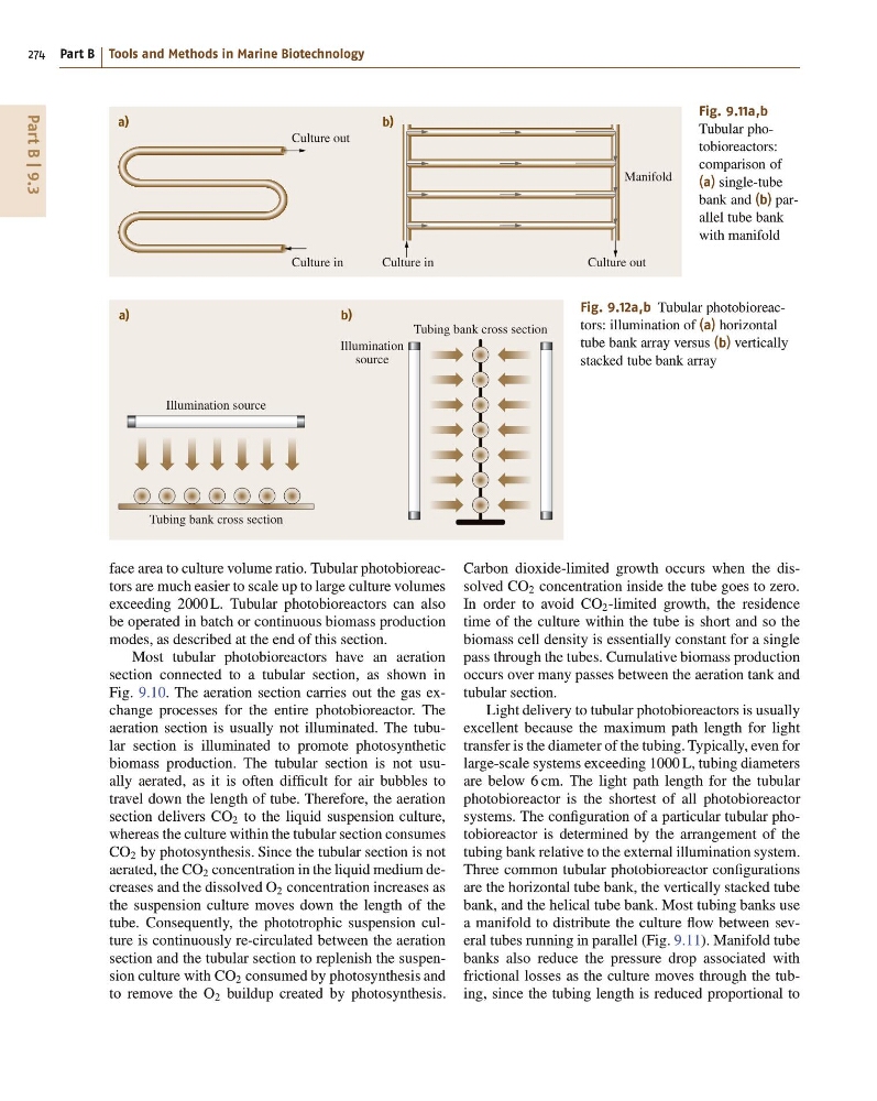
Fig. 9.11a,b
Tubular photobioreactors:
comparison of
(a) single-tube
bank and (b) parallel tube bank
with manifold
Illumination source
Tubing bank cross section
Illumination
source
Tubing bank cross section
a)
b)
Fig. 9.12a,b Tubular photobioreactors: illumination of (a) horizontal
tube bank array versus (b) vertically
stacked tube bank array
face area to culture volume ratio. Tubular photobioreactors are much easier to scale up to large culture volumes
exceeding 2000 L. Tubular photobioreactors can also
be operated in batch or continuous biomass production
modes, as described at the end of this section.
Most tubular photobioreactors have an aeration
section connected to a tubular section, as shown in
Fig. 9.10. The aeration section carries out the gas exchange processes for the entire photobioreactor. The
aeration section is usually not illuminated. The tubular section is illuminated to promote photosynthetic
biomass production. The tubular section is not usually aerated, as it is often difficult for air bubbles to
travel down the length of tube. Therefore, the aeration
section delivers CO 2 to the liquid suspension culture,
whereas the culture within the tubular section consumes
CO 2 by photosynthesis. Since the tubular section is not
aerated, the CO 2 concentration in the liquid medium decreases and the dissolved O 2 concentration increases as
the suspension culture moves down the length of the
tube. Consequently, the phototrophic suspension culture is continuously re-circulated between the aeration
section and the tubular section to replenish the suspension culture with CO 2 consumed by photosynthesis and
to remove the O 2 buildup created by photosynthesis.
Carbon dioxide-limited growth occurs when the dissolved CO 2 concentration inside the tube goes to zero.
In order to avoid CO 2 -limited growth, the residence
time of the culture within the tube is short and so the
biomass cell density is essentially constant for a single
pass through the tubes. Cumulative biomass production
occurs over many passes between the aeration tank and
tubular section.
Light delivery to tubular photobioreactors is usually
excellent because the maximum path length for light
transfer is the diameter of the tubing. Typically, even for
large-scale systems exceeding 1000 L, tubing diameters
are below 6 cm. The light path length for the tubular
photobioreactor is the shortest of all photobioreactor
systems. The configuration of a particular tubular photobioreactor is determined by the arrangement of the
tubing bank relative to the external illumination system.
Three common tubular photobioreactor configurations
are the horizontal tube bank, the vertically stacked tube
bank, and the helical tube bank. Most tubing banks use
a manifold to distribute the culture flow between several tubes running in parallel (Fig. 9.11). Manifold tube
banks also reduce the pressure drop associated with
frictional losses as the culture moves through the tubing, since the tubing length is reduced proportional to
274 Part B Tools and Methods in Marine Biotechnology
a)
b)
Culture in
Culture in
Culture out
Culture out
Manifold
Fig. 9.11a,b
Tubular photobioreactors:
comparison of
(a) single-tube
bank and (b) parallel tube bank
with manifold
Illumination source
Tubing bank cross section
Illumination
source
Tubing bank cross section
a)
b)
Fig. 9.12a,b Tubular photobioreactors: illumination of (a) horizontal
tube bank array versus (b) vertically
stacked tube bank array
face area to culture volume ratio. Tubular photobioreactors are much easier to scale up to large culture volumes
exceeding 2000 L. Tubular photobioreactors can also
be operated in batch or continuous biomass production
modes, as described at the end of this section.
Most tubular photobioreactors have an aeration
section connected to a tubular section, as shown in
Fig. 9.10. The aeration section carries out the gas exchange processes for the entire photobioreactor. The
aeration section is usually not illuminated. The tubular section is illuminated to promote photosynthetic
biomass production. The tubular section is not usually aerated, as it is often difficult for air bubbles to
travel down the length of tube. Therefore, the aeration
section delivers CO 2 to the liquid suspension culture,
whereas the culture within the tubular section consumes
CO 2 by photosynthesis. Since the tubular section is not
aerated, the CO 2 concentration in the liquid medium decreases and the dissolved O 2 concentration increases as
the suspension culture moves down the length of the
tube. Consequently, the phototrophic suspension culture is continuously re-circulated between the aeration
section and the tubular section to replenish the suspension culture with CO 2 consumed by photosynthesis and
to remove the O 2 buildup created by photosynthesis.
Carbon dioxide-limited growth occurs when the dissolved CO 2 concentration inside the tube goes to zero.
In order to avoid CO 2 -limited growth, the residence
time of the culture within the tube is short and so the
biomass cell density is essentially constant for a single
pass through the tubes. Cumulative biomass production
occurs over many passes between the aeration tank and
tubular section.
Light delivery to tubular photobioreactors is usually
excellent because the maximum path length for light
transfer is the diameter of the tubing. Typically, even for
large-scale systems exceeding 1000 L, tubing diameters
are below 6 cm. The light path length for the tubular
photobioreactor is the shortest of all photobioreactor
systems. The configuration of a particular tubular photobioreactor is determined by the arrangement of the
tubing bank relative to the external illumination system.
Three common tubular photobioreactor configurations
are the horizontal tube bank, the vertically stacked tube
bank, and the helical tube bank. Most tubing banks use
a manifold to distribute the culture flow between several tubes running in parallel (Fig. 9.11). Manifold tube
banks also reduce the pressure drop associated with
frictional losses as the culture moves through the tubing, since the tubing length is reduced proportional to