

Bioprocess Engineering of Phototrophic Marine Organisms 9.3 Basic Elements of Photobioreactor Design and Operation 273
Part B | 9.3
Illumination
source
Transparent
illumination
conduits
Air in
Air out
Impeller and
drive motor
Impeller and
drive motor
Tranparent vessel
Air in
Air out
Power unit or
fibre-optic
light source
Conventional vessel
b)
a)
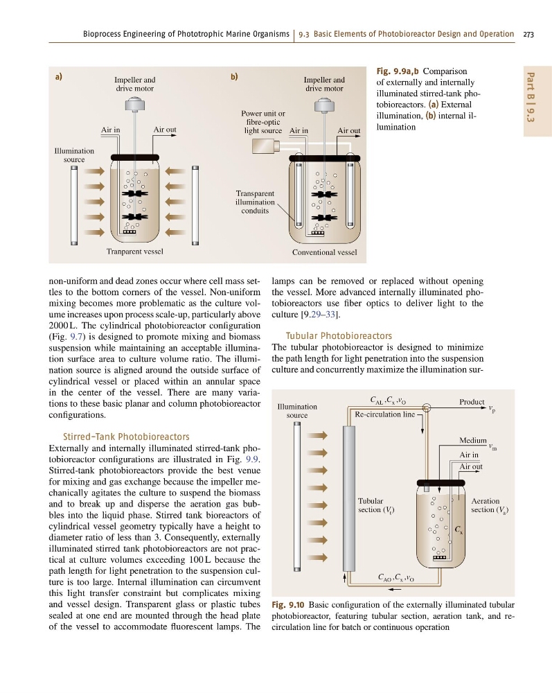
Fig. 9.9a,b Comparison
of externally and internally
illuminated stirred-tank photobioreactors. (a) External
illumination, (b) internal illumination
non-uniform and dead zones occur where cell mass settles to the bottom corners of the vessel. Non-uniform
mixing becomes more problematic as the culture volume increases upon process scale-up, particularly above
2000 L. The cylindrical photobioreactor configuration
(Fig. 9.7) is designed to promote mixing and biomass
suspension while maintaining an acceptable illumination surface area to culture volume ratio. The illumination source is aligned around the outside surface of
cylindrical vessel or placed within an annular space
in the center of the vessel. There are many variations to these basic planar and column photobioreactor
configurations.
Stirred-Tank Photobioreactors
Externally and internally illuminated stirred-tank photobioreactor configurations are illustrated in Fig. 9.9.
Stirred-tank photobioreactors provide the best venue
for mixing and gas exchange because the impeller mechanically agitates the culture to suspend the biomass
and to break up and disperse the aeration gas bubbles into the liquid phase. Stirred tank bioreactors of
cylindrical vessel geometry typically have a height to
diameter ratio of less than 3. Consequently, externally
illuminated stirred tank photobioreactors are not practical at culture volumes exceeding 100 L because the
path length for light penetration to the suspension culture is too large. Internal illumination can circumvent
this light transfer constraint but complicates mixing
and vessel design. Transparent glass or plastic tubes
sealed at one end are mounted through the head plate
of the vessel to accommodate fluorescent lamps. The
lamps can be removed or replaced without opening
the vessel. More advanced internally illuminated photobioreactors use fiber optics to deliver light to the
culture [9.29–33].
Tubular Photobioreactors
The tubular photobioreactor is designed to minimize
the path length for light penetration into the suspension
culture and concurrently maximize the illumination surIllumination
source
Air in
Medium
Re-circulation line
Product
Tubular
section (V t )
Aeration
section (V a )
v m
C x
C AO ,C x ,v O
C AL ,C x ,v O
v p
Air out
Fig. 9.10 Basic configuration of the externally illuminated tubular
photobioreactor, featuring tubular section, aeration tank, and recirculation line for batch or continuous operation
Part B | 9.3
Illumination
source
Transparent
illumination
conduits
Air in
Air out
Impeller and
drive motor
Impeller and
drive motor
Tranparent vessel
Air in
Air out
Power unit or
fibre-optic
light source
Conventional vessel
b)
a)
Fig. 9.9a,b Comparison
of externally and internally
illuminated stirred-tank photobioreactors. (a) External
illumination, (b) internal illumination
non-uniform and dead zones occur where cell mass settles to the bottom corners of the vessel. Non-uniform
mixing becomes more problematic as the culture volume increases upon process scale-up, particularly above
2000 L. The cylindrical photobioreactor configuration
(Fig. 9.7) is designed to promote mixing and biomass
suspension while maintaining an acceptable illumination surface area to culture volume ratio. The illumination source is aligned around the outside surface of
cylindrical vessel or placed within an annular space
in the center of the vessel. There are many variations to these basic planar and column photobioreactor
configurations.
Stirred-Tank Photobioreactors
Externally and internally illuminated stirred-tank photobioreactor configurations are illustrated in Fig. 9.9.
Stirred-tank photobioreactors provide the best venue
for mixing and gas exchange because the impeller mechanically agitates the culture to suspend the biomass
and to break up and disperse the aeration gas bubbles into the liquid phase. Stirred tank bioreactors of
cylindrical vessel geometry typically have a height to
diameter ratio of less than 3. Consequently, externally
illuminated stirred tank photobioreactors are not practical at culture volumes exceeding 100 L because the
path length for light penetration to the suspension culture is too large. Internal illumination can circumvent
this light transfer constraint but complicates mixing
and vessel design. Transparent glass or plastic tubes
sealed at one end are mounted through the head plate
of the vessel to accommodate fluorescent lamps. The
lamps can be removed or replaced without opening
the vessel. More advanced internally illuminated photobioreactors use fiber optics to deliver light to the
culture [9.29–33].
Tubular Photobioreactors
The tubular photobioreactor is designed to minimize
the path length for light penetration into the suspension
culture and concurrently maximize the illumination surIllumination
source
Air in
Medium
Re-circulation line
Product
Tubular
section (V t )
Aeration
section (V a )
v m
C x
C AO ,C x ,v O
C AL ,C x ,v O
v p
Air out
Fig. 9.10 Basic configuration of the externally illuminated tubular
photobioreactor, featuring tubular section, aeration tank, and recirculation line for batch or continuous operation