

327
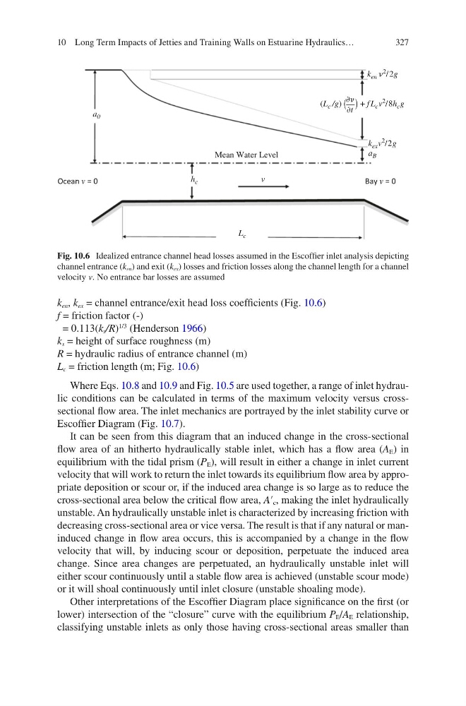
k en , k ex = channel entrance/exit head loss coefficients (Fig. 10.6)
f = friction factor (-)
= 0.113(k s /R)
1/3
(Henderson 1966)
k s = height of surface roughness (m)
R = hydraulic radius of entrance channel (m)
L c = friction length (m; Fig. 10.6)
Where Eqs. 10.8 and 10.9 and Fig. 10.5 are used together, a range of inlet hydraulic conditions can be calculated in terms of the maximum velocity versus crosssectional flow area. The inlet mechanics are portrayed by the inlet stability curve or
Escoffier Diagram (Fig. 10.7).
It can be seen from this diagram that an induced change in the cross-sectional
flow area of an hitherto hydraulically stable inlet, which has a flow area (A E ) in
equilibrium with the tidal prism (P E ), will result in either a change in inlet current
velocity that will work to return the inlet towards its equilibrium flow area by appropriate deposition or scour or, if the induced area change is so large as to reduce the
cross-sectional area below the critical flow area, A′ c , making the inlet hydraulically
unstable. An hydraulically unstable inlet is characterized by increasing friction with
decreasing cross-sectional area or vice versa. The result is that if any natural or maninduced change in flow area occurs, this is accompanied by a change in the flow
velocity that will, by inducing scour or deposition, perpetuate the induced area
change. Since area changes are perpetuated, an hydraulically unstable inlet will
either scour continuously until a stable flow area is achieved (unstable scour mode)
or it will shoal continuously until inlet closure (unstable shoaling mode).
Other interpretations of the Escoffier Diagram place significance on the first (or
lower) intersection of the “closure” curve with the equilibrium P E /A E relationship,
classifying unstable inlets as only those having cross-sectional areas smaller than
Ocean v = 0
B ay v = 0
a 0
a B
k ex v
2 /2g
k en
2 / 2g
h c
L c
v
Mean Water Level
(L c /g)
Ѩ + f L c v
2 /8h c g
Ѩt
Fig. 10.6 Idealized entrance channel head losses assumed in the Escoffier inlet analysis depicting
channel entrance (k en ) and exit (k ex ) losses and friction losses along the channel length for a channel
velocity v. No entrance bar losses are assumed
10 Long Term Impacts of Jetties and Training Walls on Estuarine Hydraulics…
k en , k ex = channel entrance/exit head loss coefficients (Fig. 10.6)
f = friction factor (-)
= 0.113(k s /R)
1/3
(Henderson 1966)
k s = height of surface roughness (m)
R = hydraulic radius of entrance channel (m)
L c = friction length (m; Fig. 10.6)
Where Eqs. 10.8 and 10.9 and Fig. 10.5 are used together, a range of inlet hydraulic conditions can be calculated in terms of the maximum velocity versus crosssectional flow area. The inlet mechanics are portrayed by the inlet stability curve or
Escoffier Diagram (Fig. 10.7).
It can be seen from this diagram that an induced change in the cross-sectional
flow area of an hitherto hydraulically stable inlet, which has a flow area (A E ) in
equilibrium with the tidal prism (P E ), will result in either a change in inlet current
velocity that will work to return the inlet towards its equilibrium flow area by appropriate deposition or scour or, if the induced area change is so large as to reduce the
cross-sectional area below the critical flow area, A′ c , making the inlet hydraulically
unstable. An hydraulically unstable inlet is characterized by increasing friction with
decreasing cross-sectional area or vice versa. The result is that if any natural or maninduced change in flow area occurs, this is accompanied by a change in the flow
velocity that will, by inducing scour or deposition, perpetuate the induced area
change. Since area changes are perpetuated, an hydraulically unstable inlet will
either scour continuously until a stable flow area is achieved (unstable scour mode)
or it will shoal continuously until inlet closure (unstable shoaling mode).
Other interpretations of the Escoffier Diagram place significance on the first (or
lower) intersection of the “closure” curve with the equilibrium P E /A E relationship,
classifying unstable inlets as only those having cross-sectional areas smaller than
Ocean v = 0
B ay v = 0
a 0
a B
k ex v
2 /2g
k en
2 / 2g
h c
L c
v
Mean Water Level
(L c /g)
Ѩ + f L c v
2 /8h c g
Ѩt
Fig. 10.6 Idealized entrance channel head losses assumed in the Escoffier inlet analysis depicting
channel entrance (k en ) and exit (k ex ) losses and friction losses along the channel length for a channel
velocity v. No entrance bar losses are assumed
10 Long Term Impacts of Jetties and Training Walls on Estuarine Hydraulics…