

18 Field Radiometry and Ocean Color Remote Sensing
317
18.4.3 Immersion Factor of In-Water Radiometers
The refractive index of the diffuser material, n d (λ), used for manufacturing irradiance collectors is always larger than the refractive index of water, n w (λ), and of air,
n a . Since n w (λ) > n a , the Fresnel reflectance of the external water-diffuser interface is smaller than that of the air-diffuser interface. Consequently, the transmission
of light through the external interface of the diffuser is larger in water than in air.
However, the internal diffuser-water interface also reflects less of the internal diffuse
light back into the diffuser, when compared to the corresponding diffuser-air interface. Thus because the increase in light transmitted back into the water is greater
than the increased amount of light transmitted from the water into the diffuser, there
is a decrease in the transmittance of the diffuser when the instrument is in water
with respect to in air.
Early studies on immersion effects for irradiance sensors were carried out by
Atkins and Poole (1933) who made an attempt to describe the internal and external reflection factors for an opal glass diffuser. Successive studies were performed
by Berger (1958, 1961) attempting a rigorous description of the physical processes involved with the optics of immersed radiometers. These results were later
used by Westlake (1965) to extensively illustrate the reflection-refraction processes
occurring at the air-diffuser and at the water-diffuser interfaces.
A comprehensive description of protocols for the experimental characterization
of the immersion factor of in-water irradiance collectors, was given by Tyler and
Smith (1970) based on the use of a collimated source, and by Aas (1969) based on
a point source. This latter method was implemented by Petzold and Austin (1988)
and applied by Mueller (1995) and Zibordi et al. (2004b), and later subject to refinements (Hooker and Zibordi, 2005a). These studies highlighted (Mueller, 1995) and
afterward confirmed (Zibordi et al., 2004b) the need for the experimental characterization of each individual irradiance collector as opposed to applying class-based
immersion factors.
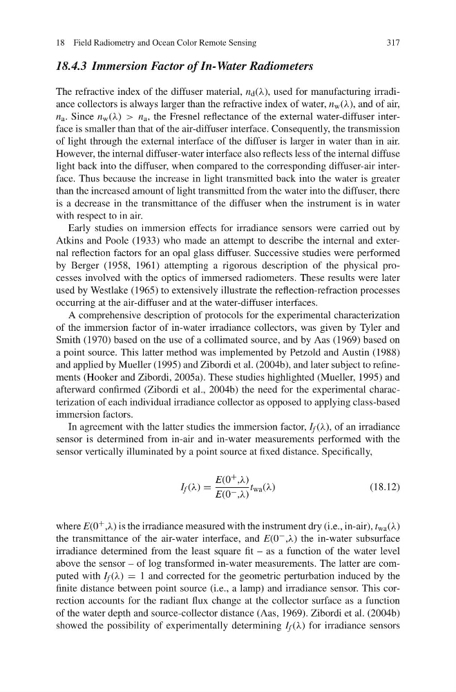
In agreement with the latter studies the immersion factor, I f (λ), of an irradiance
sensor is determined from in-air and in-water measurements performed with the
sensor vertically illuminated by a point source at fixed distance. Specifically,
I f (λ) =
E(0 + ,λ)
E(0 − ,λ)
t wa (λ)
(18.12)
where E(0 + ,λ) is the irradiance measured with the instrument dry (i.e., in-air), t wa (λ)
the transmittance of the air-water interface, and E(0 − ,λ) the in-water subsurface
irradiance determined from the least square fit – as a function of the water level
above the sensor – of log transformed in-water measurements. The latter are computed with I f (λ) = 1 and corrected for the geometric perturbation induced by the
finite distance between point source (i.e., a lamp) and irradiance sensor. This correction accounts for the radiant flux change at the collector surface as a function
of the water depth and source-collector distance (Aas, 1969). Zibordi et al. (2004b)
showed the possibility of experimentally determining I f (λ) for irradiance sensors
317
18.4.3 Immersion Factor of In-Water Radiometers
The refractive index of the diffuser material, n d (λ), used for manufacturing irradiance collectors is always larger than the refractive index of water, n w (λ), and of air,
n a . Since n w (λ) > n a , the Fresnel reflectance of the external water-diffuser interface is smaller than that of the air-diffuser interface. Consequently, the transmission
of light through the external interface of the diffuser is larger in water than in air.
However, the internal diffuser-water interface also reflects less of the internal diffuse
light back into the diffuser, when compared to the corresponding diffuser-air interface. Thus because the increase in light transmitted back into the water is greater
than the increased amount of light transmitted from the water into the diffuser, there
is a decrease in the transmittance of the diffuser when the instrument is in water
with respect to in air.
Early studies on immersion effects for irradiance sensors were carried out by
Atkins and Poole (1933) who made an attempt to describe the internal and external reflection factors for an opal glass diffuser. Successive studies were performed
by Berger (1958, 1961) attempting a rigorous description of the physical processes involved with the optics of immersed radiometers. These results were later
used by Westlake (1965) to extensively illustrate the reflection-refraction processes
occurring at the air-diffuser and at the water-diffuser interfaces.
A comprehensive description of protocols for the experimental characterization
of the immersion factor of in-water irradiance collectors, was given by Tyler and
Smith (1970) based on the use of a collimated source, and by Aas (1969) based on
a point source. This latter method was implemented by Petzold and Austin (1988)
and applied by Mueller (1995) and Zibordi et al. (2004b), and later subject to refinements (Hooker and Zibordi, 2005a). These studies highlighted (Mueller, 1995) and
afterward confirmed (Zibordi et al., 2004b) the need for the experimental characterization of each individual irradiance collector as opposed to applying class-based
immersion factors.
In agreement with the latter studies the immersion factor, I f (λ), of an irradiance
sensor is determined from in-air and in-water measurements performed with the
sensor vertically illuminated by a point source at fixed distance. Specifically,
I f (λ) =
E(0 + ,λ)
E(0 − ,λ)
t wa (λ)
(18.12)
where E(0 + ,λ) is the irradiance measured with the instrument dry (i.e., in-air), t wa (λ)
the transmittance of the air-water interface, and E(0 − ,λ) the in-water subsurface
irradiance determined from the least square fit – as a function of the water level
above the sensor – of log transformed in-water measurements. The latter are computed with I f (λ) = 1 and corrected for the geometric perturbation induced by the
finite distance between point source (i.e., a lamp) and irradiance sensor. This correction accounts for the radiant flux change at the collector surface as a function
of the water depth and source-collector distance (Aas, 1969). Zibordi et al. (2004b)
showed the possibility of experimentally determining I f (λ) for irradiance sensors