

318
G. Zibordi and K.J. Voss
with an uncertainty of approximately 0.5% for values falling in a typical range of
1.35–1.40.
The responsivity of radiance sensors also changes when operated in water as
opposed to air due to the relative change in the solid angle field–of–view (depending on radiometer design) and the variation of reflectance and transmittance of the
optical window (because the refractive index n g (λ) of the window is different from
that of the air or water). I f (λ) for radiance sensors is commonly derived theoretically
unlike that of irradiance sensors which can only be determined experimentally. A
general model proposed by Austin (1976) for determining I f (λ) for radiance sensors
simply relies on the knowledge of the refractive indices of seawater and that of the
radiometer’s window.
The alternative possibility of experimentally characterizing I f (λ) for radiance
sensors was recently documented by Zibordi (2006). The application of the
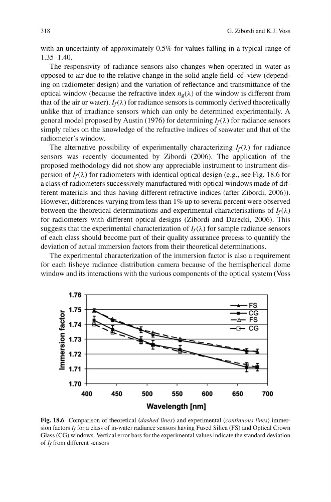
proposed methodology did not show any appreciable instrument to instrument dispersion of I f (λ) for radiometers with identical optical design (e.g., see Fig. 18.6 for
a class of radiometers successively manufactured with optical windows made of different materials and thus having different refractive indices (after Zibordi, 2006)).
However, differences varying from less than 1% up to several percent were observed
between the theoretical determinations and experimental characterisations of I f (λ)
for radiometers with different optical designs (Zibordi and Darecki, 2006). This
suggests that the experimental characterization of I f (λ) for sample radiance sensors
of each class should become part of their quality assurance process to quantify the
deviation of actual immersion factors from their theoretical determinations.
The experimental characterization of the immersion factor is also a requirement
for each fisheye radiance distribution camera because of the hemispherical dome
window and its interactions with the various components of the optical system (Voss
Fig. 18.6 Comparison of theoretical (dashed lines) and experimental (continuous lines) immersion factors I f for a class of in-water radiance sensors having Fused Silica (FS) and Optical Crown
Glass (CG) windows. Vertical error bars for the experimental values indicate the standard deviation
of I f from different sensors
G. Zibordi and K.J. Voss
with an uncertainty of approximately 0.5% for values falling in a typical range of
1.35–1.40.
The responsivity of radiance sensors also changes when operated in water as
opposed to air due to the relative change in the solid angle field–of–view (depending on radiometer design) and the variation of reflectance and transmittance of the
optical window (because the refractive index n g (λ) of the window is different from
that of the air or water). I f (λ) for radiance sensors is commonly derived theoretically
unlike that of irradiance sensors which can only be determined experimentally. A
general model proposed by Austin (1976) for determining I f (λ) for radiance sensors
simply relies on the knowledge of the refractive indices of seawater and that of the
radiometer’s window.
The alternative possibility of experimentally characterizing I f (λ) for radiance
sensors was recently documented by Zibordi (2006). The application of the
proposed methodology did not show any appreciable instrument to instrument dispersion of I f (λ) for radiometers with identical optical design (e.g., see Fig. 18.6 for
a class of radiometers successively manufactured with optical windows made of different materials and thus having different refractive indices (after Zibordi, 2006)).
However, differences varying from less than 1% up to several percent were observed
between the theoretical determinations and experimental characterisations of I f (λ)
for radiometers with different optical designs (Zibordi and Darecki, 2006). This
suggests that the experimental characterization of I f (λ) for sample radiance sensors
of each class should become part of their quality assurance process to quantify the
deviation of actual immersion factors from their theoretical determinations.
The experimental characterization of the immersion factor is also a requirement
for each fisheye radiance distribution camera because of the hemispherical dome
window and its interactions with the various components of the optical system (Voss
Fig. 18.6 Comparison of theoretical (dashed lines) and experimental (continuous lines) immersion factors I f for a class of in-water radiance sensors having Fused Silica (FS) and Optical Crown
Glass (CG) windows. Vertical error bars for the experimental values indicate the standard deviation
of I f from different sensors