

fracture zones, can expose sections of the entire crust.
Between these dominant faults, segments can also be separated by non-transform offsets. Commonly located at the
internal corner between ridge and fracture zones, longlived detachment faults tend to generate oceanic core complexes (OCC), described below (Figure 13), although
OCC have also been observed within segments (Escartin
et al., 2008).
Structure
Because of faulting and rotation of blocks in OCC, the seafloor morphology of the crust formed at slow spreading
ridges is very irregular and rugged. For this reason, only
limited combined seismic reflection and refraction studies
have been successful; the best results were obtained at the
Lucky Strike segment of the Mid-Atlantic Ridge
(Crawford et al., 2010). Layer 2A in this area is thicker
(400–800 m) than that at fast spreading centers, which
could be due to the accumulation of lava flow over a long
time and slow spreading. The thick layer 2A could also
result from a complex interaction of lava flow, faulting,
and hydrothermal circulation. At the Lucky Strike segment, layer 2A does not seem to vary along the ridge axis,
indicating that the thickness of layer 2A remains constant
along the whole 70 km long segment, suggesting that volcanism plays an important role along the whole segment.
The thickness of layer 2A decreases around the bounding
faults, suggesting that the tectonic processes could
decrease the thickness of volcanically constructed crust.
The imaging of layer 2B is rather difficult beneath slow
spreading ridges because of the absence of AML in the
crust and complex accretion process. However, a
3–4 km wide and 7 km long AML was recently imaged
at the center of the Lucky Strike segment at ~3 km depth
(Singh et al., 2006b) for the first time, suggesting that
layer 2B there could be 2–2.5 km thick (Figure 11). There
is a low velocity beneath the AML, which could be due to
the partial melt in the lower crust, but the percentage of
melt is much less than that observed at fast spreading centers (Dunn et al., 2000). The presence of AML also allows
to characterize the lower crust, layer 3, which in the Lucky
Strike area is about 3–4 km thick, leading to a crustal
thickness of 7 km at the center of the segment (Seher et al.,
2010). The crustal thickness at the segment ends smoothly
decreases to 5 km, suggesting the crust at slow spreading
centers are boudin shaped, i.e., thick in the center of segment and thin at segments end.
Seismic reflection images at the Lucky Strike segment
also show faults that penetrate down to AML, which
include not just the median valley bounding faults but
many other faults within the axis (Figure 11). As
expected, these faults are ridge-ward dipping. These
faults could be responsible for hydrothermal circulation
and may influence the positions of hydrothermal vent
fields.
hydrothermal
plumbing
black smoker
sheeted dikes
perched melt lens
wehrlite sill
lava mound
d u n i t e
5KM
5KM
harzburgite
M T Z
mantle diapir
0
gabbro sill
g a b b r o m a g m a c h a m b e r
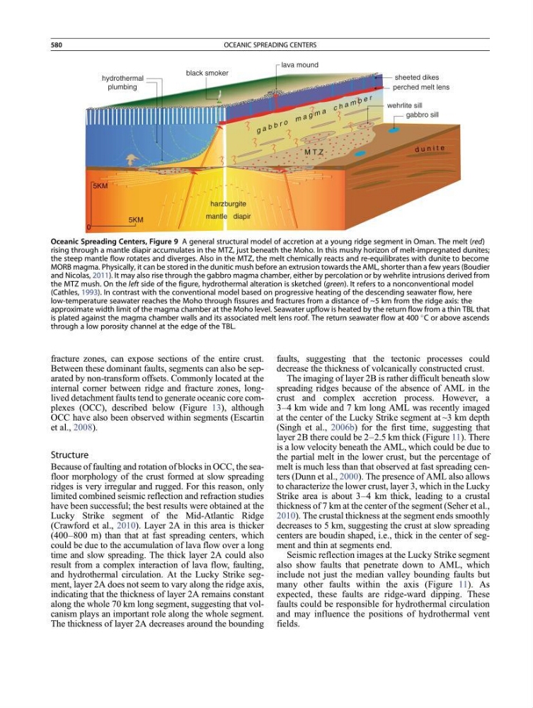
Oceanic Spreading Centers, Figure 9 A general structural model of accretion at a young ridge segment in Oman. The melt (red)
rising through a mantle diapir accumulates in the MTZ, just beneath the Moho. In this mushy horizon of melt-impregnated dunites;
the steep mantle flow rotates and diverges. Also in the MTZ, the melt chemically reacts and re-equilibrates with dunite to become
MORB magma. Physically, it can be stored in the dunitic mush before an extrusion towards the AML, shorter than a few years (Boudier
and Nicolas, 2011). It may also rise through the gabbro magma chamber, either by percolation or by wehrlite intrusions derived from
the MTZ mush. On the left side of the figure, hydrothermal alteration is sketched (green). It refers to a nonconventional model
(Cathles, 1993). In contrast with the conventional model based on progressive heating of the descending seawater flow, here
low-temperature seawater reaches the Moho through fissures and fractures from a distance of ~5 km from the ridge axis: the
approximate width limit of the magma chamber at the Moho level. Seawater upflow is heated by the return flow from a thin TBL that
is plated against the magma chamber walls and its associated melt lens roof. The return seawater flow at 400
C or above ascends
through a low porosity channel at the edge of the TBL.
580
OCEANIC SPREADING CENTERS