

Morphology
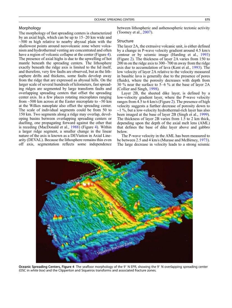
The morphology of fast spreading centers is characterized
by an axial high, which can be up to 15–20 km wide and
~500 m high relative to nearby abyssal plain with the
shallowest points around neovolcanic zone where volcanism and hydrothermal venting are concentrated and often
have a region of volcanic collapse at the center (Figure 4).
The presence of axial highs is due to the upwelling of hot
mantle beneath the spreading centers. The lithosphere
exactly beneath the ridge axis is limited to the lid itself,
and therefore, very few faults are observed, but as the lithosphere drifts and thickens, some faults develop away
from the ridge that are expressed as abyssal hills. On the
larger scale of several hundreds of kilometers, fast spreading ridges are segmented by large transform faults and
overlapping spreading centers that offset the spreading
center axis. In a few places rotating microplates ranging
from ~500 km across at the Easter microplate to ~50 km
at the Wilkes nanoplate also offset the spreading center.
The scale of individual segments could be from 50 to
150 km. Two segments along a ridge may overlap, developing basins between overlapping spreading centers or
duelling, one propagating forward against the other that
is receding (MacDonald et al., 1988) (Figure 4). Within
a larger ridge segment, a smaller change in the linear
nature of the axis is known as a DEViation in Axial Linearity (DEVAL). Because the lithosphere remains thin even
off axis, segmentation reflects some independence
between lithospheric and asthenospheric tectonic activity
(Toomey et al., 2007).
Structure
The layer 2A, the extrusive volcanic unit, is either defined
by a change in P-wave velocity gradient around 4.5 km/s
contour or by seismic image (Harding et al., 1993)
(Figure 2). The thickness of layer 2A varies from 150 to
200 m on the ridge axis to 300–700 m away from the ridge
axis due to accumulation of lava (Kent et al., 1993). The
low velocity of layer 2A relative to the velocity measured
in basaltic lava is generally due to the presence of pores
(fluids), where the porosity decreases with depth from
30 % near the surface to 5–6 % at the base of layer 2A
(Collier and Singh, 1998).
Layer 2B, the sheeted dike layer, is defined by a
low-velocity gradient layer, where the P-wave velocity
ranges from 4.5 to 6 km/s (Figure 2). The presence of high
velocity suggests a further decrease of porosity down to
~1 %, but a low-velocity hydrothermal-rich layer has also
been imaged at the base of layer 2B (Singh et al., 1999).
The thickness of layer 2B varies from 1.5 to 2 km thick,
depending upon the depth of the axial melt lens (AML)
that defines the base of dike layer above and gabbro
below.
The P-wave velocity in the AML has been measured to
be between 2.5 and 4 km/s (Murase and McBirney, 1973).
The large decrease in velocity leads to a strong seismic
Oceanic Spreading Centers, Figure 4 The seafloor morphology of the 9
N EPR, showing the 9
N overlapping spreading center
(OSC in white box) and the Clipperton and Siqueiros transforms and associated fracture zones.
OCEANIC SPREADING CENTERS
575