

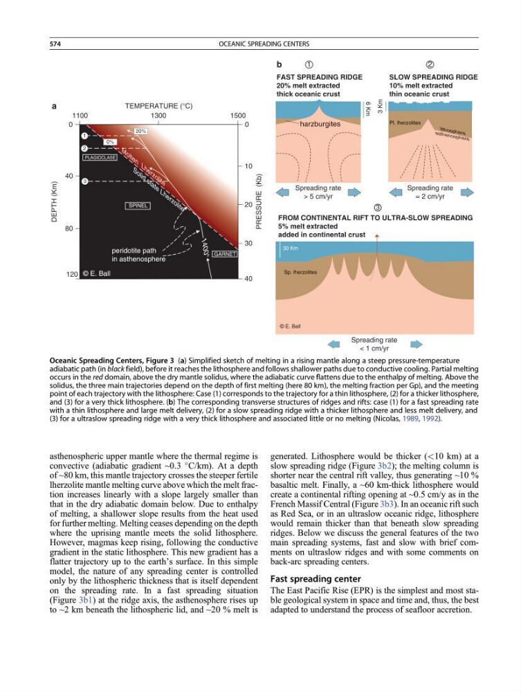
asthenospheric upper mantle where the thermal regime is
convective (adiabatic gradient ~0.3
C/km). At a depth
of ~80 km, this mantle trajectory crosses the steeper fertile
lherzolite mantle melting curve above which the melt fraction increases linearly with a slope largely smaller than
that in the dry adiabatic domain below. Due to enthalpy
of melting, a shallower slope results from the heat used
for further melting. Melting ceases depending on the depth
where the uprising mantle meets the solid lithosphere.
However, magmas keep rising, following the conductive
gradient in the static lithosphere. This new gradient has a
flatter trajectory up to the earth’s surface. In this simple
model, the nature of any spreading center is controlled
only by the lithospheric thickness that is itself dependent
on the spreading rate. In a fast spreading situation
(Figure 3b1) at the ridge axis, the asthenosphere rises up
to ~2 km beneath the lithospheric lid, and ~20 % melt is
generated. Lithosphere would be thicker (<10 km) at a
slow spreading ridge (Figure 3b2); the melting column is
shorter near the central rift valley, thus generating ~10 %
basaltic melt. Finally, a ~60 km-thick lithosphere would
create a continental rifting opening at ~0.5 cm/y as in the
French Massif Central (Figure 3b3). In an oceanic rift such
as Red Sea, or in an ultraslow oceanic ridge, lithosphere
would remain thicker than that beneath slow spreading
ridges. Below we discuss the general features of the two
main spreading systems, fast and slow with brief comments on ultraslow ridges and with some comments on
back-arc spreading centers.
Fast spreading center
The East Pacific Rise (EPR) is the simplest and most stable geological system in space and time and, thus, the best
adapted to understand the process of seafloor accretion.
14
00
°
S o l i d s t a t e L h e r z o l i t e
M o l t e n L h e r z o l i t e
120
PRESSURE
(Kb)
TEMPERATURE (°C)
DEPTH
(Km)
0%
SPINEL
PLAGIOCLASE
20%
© E. Ball
3
2
1
FROM CONTINENTAL RIFT TO ULTRA-SLOW SPREADING
5% melt extracted
added in continental crust
Spreading rate
< 1 cm/yr
30 Km
Sp. lherzolites
© E. Ball
FAST SPREADING RIDGE
20% melt extracted
thick oceanic crust
Pl. lherzolites
lith os ph ere
as the no sp he re
harzburgites
Spreading rate
> 5 cm/yr
SLOW SPREADING RIDGE
10% melt extracted
thin oceanic crust
Spreading rate
= 2 cm/yr
6 Km
3 Km
1
2
3
80
40
0
10
20
30
40
0
GARNET
1100
a
b
1300
1500
peridotite path
in asthenosphere
Oceanic Spreading Centers, Figure 3 (a) Simplified sketch of melting in a rising mantle along a steep pressure-temperature
adiabatic path (in black field), before it reaches the lithosphere and follows shallower paths due to conductive cooling. Partial melting
occurs in the red domain, above the dry mantle solidus, where the adiabatic curve flattens due to the enthalpy of melting. Above the
solidus, the three main trajectories depend on the depth of first melting (here 80 km), the melting fraction per Gp), and the meeting
point of each trajectory with the lithosphere: Case (1) corresponds to the trajectory for a thin lithosphere, (2) for a thicker lithosphere,
and (3) for a very thick lithosphere. (b) The corresponding transverse structures of ridges and rifts: case (1) for a fast spreading rate
with a thin lithosphere and large melt delivery, (2) for a slow spreading ridge with a thicker lithosphere and less melt delivery, and
(3) for a ultraslow spreading ridge with a very thick lithosphere and associated little or no melting (Nicolas, 1989, 1992).
574
OCEANIC SPREADING CENTERS