

10 Applications of the Inverse Problem of Pollution Propagation
349
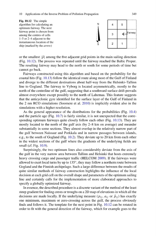
Fig. 10.12 The simple
algorithm for calculating an
optimum fairway. The next
fairway point is chosen from
among the centres of cells
1–5 or 2–4 adjacent to the
instantaneous location of the
ship (marked by the arrow)
or the smallest | ˆ
p| among the five adjacent grid points in the main sailing direction
(Fig. 10.12). The process was repeated until the fairway reached the Baltic Proper.
The resulting fairway may head to the north or south for some periods of time but
cannot go back.
Fairways constructed using this algorithm and based on the probability for the
coastal hits (Fig. 10.13) follow the identical route along most of the Gulf of Finland
and diverge to the different destinations about half-way from the Helsinki–Tallinn
line to Gogland. The fairway to Vyborg is located asymmetrically, mostly to the
north of the centreline of the gulf, suggesting that a southward surface drift prevails
almost everywhere except possibly to the north of Lahemaa. This feature suggests
that the anticyclonic gyre identified for the surface layer of the Gulf of Finland in
the 2 nm RCO simulations (Soomere et al. 2010) is implicitly evident also in the
simulations with a higher resolution.
As the general appearance of the distributions for the probabilities (Fig. 10.4)
and the particle age (Fig. 10.7) is fairly similar, it is not unexpected that the corresponding optimum fairways quite closely follow each other (Fig. 10.13). They are
mostly located to the north of the gulf axis (by 2–8 km on average) and meander
substantially in some sections. They almost overlap in the relatively narrow part of
the gulf between Naissaar and Porkkala and in narrow passages between islands,
e.g., to the south of Gogland (Fig. 10.2). They deviate up to 20 km from each other
in the widest sections of the gulf where the gradients of the underlying fields are
small (cf. Fig. 10.9).
Surprisingly, the two optimum lines also considerably deviate from the axis of
the gulf in the very narrow area between Tallinn and Helsinki that hosts extremely
heavy crossing cargo and passenger traffic (HELCOM 2009). If the fairways were
allowed to exert local turns by up to 135 ◦ , they may follow a northern route between
Gogland and the Finnish archipelago. Such a large difference between the results of
quite similar methods of fairway construction highlights the influence of the local
decision at each grid cell on the overall shape and parameters of the optimum sailing
line and certainly calls for the implementation of more elaborated approaches to
specify a globally optimized fairway.
In essence, the described procedure is a discrete variant of the method of the least
steep gradient for finding crests or troughs on a 2D map of elevations in which all the
decisions are made locally. If the underlying measure (p ij , a ij or ˆ
p ij ) has exactly
one minimum, maximum or zero-crossing across the gulf, the process obviously
finds and follows it. The template for the next point in Fig. 10.12 can be rotated in
order to fit with the general direction of the fairway, which for example goes to the
349
Fig. 10.12 The simple
algorithm for calculating an
optimum fairway. The next
fairway point is chosen from
among the centres of cells
1–5 or 2–4 adjacent to the
instantaneous location of the
ship (marked by the arrow)
or the smallest | ˆ
p| among the five adjacent grid points in the main sailing direction
(Fig. 10.12). The process was repeated until the fairway reached the Baltic Proper.
The resulting fairway may head to the north or south for some periods of time but
cannot go back.
Fairways constructed using this algorithm and based on the probability for the
coastal hits (Fig. 10.13) follow the identical route along most of the Gulf of Finland
and diverge to the different destinations about half-way from the Helsinki–Tallinn
line to Gogland. The fairway to Vyborg is located asymmetrically, mostly to the
north of the centreline of the gulf, suggesting that a southward surface drift prevails
almost everywhere except possibly to the north of Lahemaa. This feature suggests
that the anticyclonic gyre identified for the surface layer of the Gulf of Finland in
the 2 nm RCO simulations (Soomere et al. 2010) is implicitly evident also in the
simulations with a higher resolution.
As the general appearance of the distributions for the probabilities (Fig. 10.4)
and the particle age (Fig. 10.7) is fairly similar, it is not unexpected that the corresponding optimum fairways quite closely follow each other (Fig. 10.13). They are
mostly located to the north of the gulf axis (by 2–8 km on average) and meander
substantially in some sections. They almost overlap in the relatively narrow part of
the gulf between Naissaar and Porkkala and in narrow passages between islands,
e.g., to the south of Gogland (Fig. 10.2). They deviate up to 20 km from each other
in the widest sections of the gulf where the gradients of the underlying fields are
small (cf. Fig. 10.9).
Surprisingly, the two optimum lines also considerably deviate from the axis of
the gulf in the very narrow area between Tallinn and Helsinki that hosts extremely
heavy crossing cargo and passenger traffic (HELCOM 2009). If the fairways were
allowed to exert local turns by up to 135 ◦ , they may follow a northern route between
Gogland and the Finnish archipelago. Such a large difference between the results of
quite similar methods of fairway construction highlights the influence of the local
decision at each grid cell on the overall shape and parameters of the optimum sailing
line and certainly calls for the implementation of more elaborated approaches to
specify a globally optimized fairway.
In essence, the described procedure is a discrete variant of the method of the least
steep gradient for finding crests or troughs on a 2D map of elevations in which all the
decisions are made locally. If the underlying measure (p ij , a ij or ˆ
p ij ) has exactly
one minimum, maximum or zero-crossing across the gulf, the process obviously
finds and follows it. The template for the next point in Fig. 10.12 can be rotated in
order to fit with the general direction of the fairway, which for example goes to the