

20
H. Rott
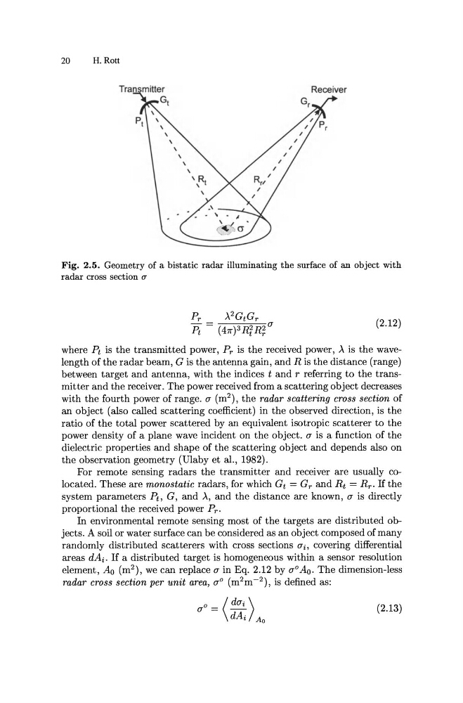
Fig. 2.5. Geometry of a bistatic radar illuminating the surface of an object with
radar cross section (J'
).,2 GtG r
(47r)3 RF R(
(2.12)
where Pt is the transmitted power, Pr is the received power, )., is the wavelength of the radar beam, G is the antenna gain, and R is the distance (range)
between target and antenna, with the indices t and r referring to the transmitter and the receiver. The power received from a scattering object decreases
with the fourth power of range. a (m 2 ), the radar scattering cross section of
an object (also called scattering coefficient) in the observed direction, is the
ratio of the total power scattered by an equivalent isotropic scatterer to the
power density of a plane wave incident on the object. a is a function of the
dielectric properties and shape of the scattering object and depends also on
the observation geometry (Ulaby et aI., 1982).
For remote sensing radars the transmitter and receiver are usually colocated. These are monostatic radars, for which Gt = Gr and R t = R r . If the
system parameters Ph G, and )." and the distance are known, a is directly
proportional the received power Pro
In environmental remote sensing most of the targets are distributed objects. A soil or water surface can be considered as an object composed of many
randomly distributed scatterers with cross sections ai, covering differential
areas dAi . If a distributed target is homogeneous within a sensor resolution
element, Ao (m 2 ), we can replace a in Eq. 2.12 by a O Ao. The dimension-less
radar cross section per unit area, a O (m 2 m- 2 ), is defined as:
(2.13)
H. Rott
Fig. 2.5. Geometry of a bistatic radar illuminating the surface of an object with
radar cross section (J'
).,2 GtG r
(47r)3 RF R(
(2.12)
where Pt is the transmitted power, Pr is the received power, )., is the wavelength of the radar beam, G is the antenna gain, and R is the distance (range)
between target and antenna, with the indices t and r referring to the transmitter and the receiver. The power received from a scattering object decreases
with the fourth power of range. a (m 2 ), the radar scattering cross section of
an object (also called scattering coefficient) in the observed direction, is the
ratio of the total power scattered by an equivalent isotropic scatterer to the
power density of a plane wave incident on the object. a is a function of the
dielectric properties and shape of the scattering object and depends also on
the observation geometry (Ulaby et aI., 1982).
For remote sensing radars the transmitter and receiver are usually colocated. These are monostatic radars, for which Gt = Gr and R t = R r . If the
system parameters Ph G, and )." and the distance are known, a is directly
proportional the received power Pro
In environmental remote sensing most of the targets are distributed objects. A soil or water surface can be considered as an object composed of many
randomly distributed scatterers with cross sections ai, covering differential
areas dAi . If a distributed target is homogeneous within a sensor resolution
element, Ao (m 2 ), we can replace a in Eq. 2.12 by a O Ao. The dimension-less
radar cross section per unit area, a O (m 2 m- 2 ), is defined as:
(2.13)