

Chapter 1: INTRODUCTION
crest, it traps enough air bubbles for the resulting air-water mixture to be
significantly lighter than the water below it. This density difference inhibits
mixing with the face of the wave, so that the whitecap rides on top of the
sloping sea surface. Accordingly, Longuet-Higgins and Turner (1974)
proposed treating a spilling breaker as a turbulent gravity current riding
down the forward slope of a wave in the same way a turbulent gravity
current rides down a solid slopping boundary (Figure 1-13). As the flow
continues, the turbulence leads to the entrainment of water from the wave
surface below. This results in further incorporation of air, especially near the
front of the whitecap, maintaining the density difference.
In the Longuet-Higgins and Turner (1974) model, the mean thickness of
the whitecap G increases proportionally to distance s from the wave crest,
while the whitecap accelerates down the slope. For maintaining the
stationary state of the wave breaker corresponding to the limiting Stokes
wave with a 120
o angle at the crest (T = 30
o ), U’ should be at least 8% less
than U.
The behavior of the spilling breaker depends on wavelength. For long
waves, the wave breaking processes results in the appearance of a turbulent
patch of fluid on the forward slope of the wave (as schematically shown in
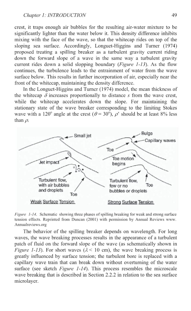
Figure 1-13). For short waves (O< 10 cm), the wave breaking process is
greatly influenced by surface tension; the turbulent bore is replaced with a
capillary wave train that can break down without overturning of the water
surface (see sketch Figure 1-14). This process resembles the microscale
wave breaking that is described in Section 2.2.2 in relation to the sea surface
microlayer.
49
Figure 1-14. Schematic showing three phases of spilling breaking for weak and strong surface
tension effects. Reprinted from Duncan (2001) with permission by Annual Reviews www.
Annualreviews.org
crest, it traps enough air bubbles for the resulting air-water mixture to be
significantly lighter than the water below it. This density difference inhibits
mixing with the face of the wave, so that the whitecap rides on top of the
sloping sea surface. Accordingly, Longuet-Higgins and Turner (1974)
proposed treating a spilling breaker as a turbulent gravity current riding
down the forward slope of a wave in the same way a turbulent gravity
current rides down a solid slopping boundary (Figure 1-13). As the flow
continues, the turbulence leads to the entrainment of water from the wave
surface below. This results in further incorporation of air, especially near the
front of the whitecap, maintaining the density difference.
In the Longuet-Higgins and Turner (1974) model, the mean thickness of
the whitecap G increases proportionally to distance s from the wave crest,
while the whitecap accelerates down the slope. For maintaining the
stationary state of the wave breaker corresponding to the limiting Stokes
wave with a 120
o angle at the crest (T = 30
o ), U’ should be at least 8% less
than U.
The behavior of the spilling breaker depends on wavelength. For long
waves, the wave breaking processes results in the appearance of a turbulent
patch of fluid on the forward slope of the wave (as schematically shown in
Figure 1-13). For short waves (O< 10 cm), the wave breaking process is
greatly influenced by surface tension; the turbulent bore is replaced with a
capillary wave train that can break down without overturning of the water
surface (see sketch Figure 1-14). This process resembles the microscale
wave breaking that is described in Section 2.2.2 in relation to the sea surface
microlayer.
49
Figure 1-14. Schematic showing three phases of spilling breaking for weak and strong surface
tension effects. Reprinted from Duncan (2001) with permission by Annual Reviews www.
Annualreviews.org