

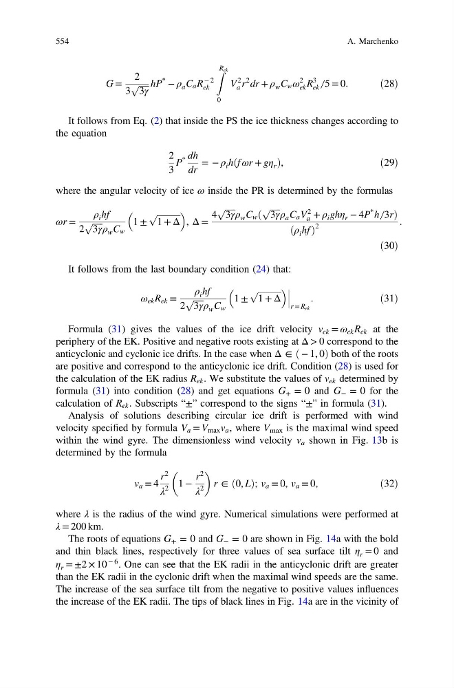
G =
2
3
ffiffiffiffiffi
3γ
p hP
*
− ρ a C a R
− 2
ek
Z R ek
0
V
2
a r
2 dr + ρ w C w ω
2
ek R
3
ek ̸ 5 = 0.
ð28Þ
It follows from Eq. (2) that inside the PS the ice thickness changes according to
the equation
2
3
P
* dh
dr
= − ρ i hðf ωr + gη r Þ,
ð29Þ
where the angular velocity of ice ω inside the PR is determined by the formulas
ωr =
ρ i hf
2
ffiffiffiffiffi
3γ
p ρ w C w
1 ±
ffiffiffiffiffiffiffiffiffiffiffi
1 + Δ
p
, Δ =
4
ffiffiffiffiffi
3γ
p ρ w C w ð
ffiffiffiffiffi
3γ
p ρ a C a V
2
a + ρ i ghη r − 4P
* h ̸ 3rÞ
ðρ i hf Þ
2
.
ð30Þ
It follows from the last boundary condition (24) that:
ω ek R ek =
ρ i hf
2
ffiffiffiffiffi
3γ
p ρ w C w
1 ±
ffiffiffiffiffiffiffiffiffiffiffi
1 + Δ
p
r = R ek
.
ð31Þ
Formula (31) gives the values of the ice drift velocity v ek = ω ek R ek at the
periphery of the EK. Positive and negative roots existing at Δ > 0 correspond to the
anticyclonic and cyclonic ice drifts. In the case when Δ ∈ ð − 1, 0Þ both of the roots
are positive and correspond to the anticyclonic ice drift. Condition (28) is used for
the calculation of the EK radius R ek . We substitute the values of v ek determined by
formula (31) into condition (28) and get equations G + = 0 and G − = 0 for the
calculation of R ek . Subscripts “±” correspond to the signs “±” in formula (31).
Analysis of solutions describing circular ice drift is performed with wind
velocity specified by formula V a = V max v a , where V max is the maximal wind speed
within the wind gyre. The dimensionless wind velocity v a shown in Fig. 13b is
determined by the formula
v a = 4
r
2
λ
2
1 −
r
2
λ
2
r ∈ ð0, LÞ; v a = 0, v a = 0,
ð32Þ
where λ is the radius of the wind gyre. Numerical simulations were performed at
λ = 200 km.
The roots of equations G + = 0 and G − = 0 are shown in Fig. 14a with the bold
and thin black lines, respectively for three values of sea surface tilt η r = 0 and
η r = ±2 × 10
− 6 . One can see that the EK radii in the anticyclonic drift are greater
than the EK radii in the cyclonic drift when the maximal wind speeds are the same.
The increase of the sea surface tilt from the negative to positive values influences
the increase of the EK radii. The tips of black lines in Fig. 14a are in the vicinity of
554
A. Marchenko
2
3
ffiffiffiffiffi
3γ
p hP
*
− ρ a C a R
− 2
ek
Z R ek
0
V
2
a r
2 dr + ρ w C w ω
2
ek R
3
ek ̸ 5 = 0.
ð28Þ
It follows from Eq. (2) that inside the PS the ice thickness changes according to
the equation
2
3
P
* dh
dr
= − ρ i hðf ωr + gη r Þ,
ð29Þ
where the angular velocity of ice ω inside the PR is determined by the formulas
ωr =
ρ i hf
2
ffiffiffiffiffi
3γ
p ρ w C w
1 ±
ffiffiffiffiffiffiffiffiffiffiffi
1 + Δ
p
, Δ =
4
ffiffiffiffiffi
3γ
p ρ w C w ð
ffiffiffiffiffi
3γ
p ρ a C a V
2
a + ρ i ghη r − 4P
* h ̸ 3rÞ
ðρ i hf Þ
2
.
ð30Þ
It follows from the last boundary condition (24) that:
ω ek R ek =
ρ i hf
2
ffiffiffiffiffi
3γ
p ρ w C w
1 ±
ffiffiffiffiffiffiffiffiffiffiffi
1 + Δ
p
r = R ek
.
ð31Þ
Formula (31) gives the values of the ice drift velocity v ek = ω ek R ek at the
periphery of the EK. Positive and negative roots existing at Δ > 0 correspond to the
anticyclonic and cyclonic ice drifts. In the case when Δ ∈ ð − 1, 0Þ both of the roots
are positive and correspond to the anticyclonic ice drift. Condition (28) is used for
the calculation of the EK radius R ek . We substitute the values of v ek determined by
formula (31) into condition (28) and get equations G + = 0 and G − = 0 for the
calculation of R ek . Subscripts “±” correspond to the signs “±” in formula (31).
Analysis of solutions describing circular ice drift is performed with wind
velocity specified by formula V a = V max v a , where V max is the maximal wind speed
within the wind gyre. The dimensionless wind velocity v a shown in Fig. 13b is
determined by the formula
v a = 4
r
2
λ
2
1 −
r
2
λ
2
r ∈ ð0, LÞ; v a = 0, v a = 0,
ð32Þ
where λ is the radius of the wind gyre. Numerical simulations were performed at
λ = 200 km.
The roots of equations G + = 0 and G − = 0 are shown in Fig. 14a with the bold
and thin black lines, respectively for three values of sea surface tilt η r = 0 and
η r = ±2 × 10
− 6 . One can see that the EK radii in the anticyclonic drift are greater
than the EK radii in the cyclonic drift when the maximal wind speeds are the same.
The increase of the sea surface tilt from the negative to positive values influences
the increase of the EK radii. The tips of black lines in Fig. 14a are in the vicinity of
554
A. Marchenko