

constructed solutions do not reflect any real situations but can explain some features
of more realistic solutions describing the wind drift of ice.
Wind Induced Zonal Ice Drift
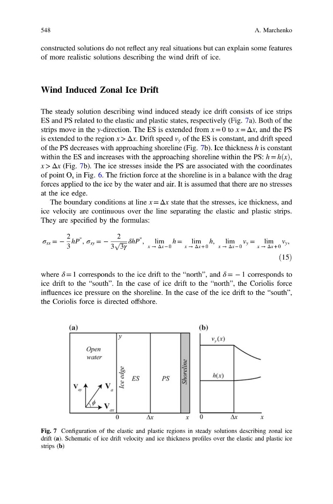
The steady solution describing wind induced steady ice drift consists of ice strips
ES and PS related to the elastic and plastic states, respectively (Fig. 7a). Both of the
strips move in the y-direction. The ES is extended from x = 0 to x = Δx, and the PS
is extended to the region x > Δx. Drift speed v y of the ES is constant, and drift speed
of the PS decreases with approaching shoreline (Fig. 7b). Ice thickness h is constant
within the ES and increases with the approaching shoreline within the PS: h = hðxÞ,
x > Δx (Fig. 7b). The ice stresses inside the PS are associated with the coordinates
of point O s in Fig. 6. The friction force at the shoreline is in a balance with the drag
forces applied to the ice by the water and air. It is assumed that there are no stresses
at the ice edge.
The boundary conditions at line x = Δx state that the stresses, ice thickness, and
ice velocity are continuous over the line separating the elastic and plastic strips.
They are specified by the formulas:
σ xx = −
2
3
hP
* , σ xy = −
2
3
ffiffiffiffiffi
3γ
p δhP
* , lim
x → Δx − 0
h = lim
x → Δx + 0
h, lim
x → Δx − 0
v y = lim
x → Δx + 0
v y ,
ð15Þ
where δ = 1 corresponds to the ice drift to the “north”, and δ = − 1 corresponds to
ice drift to the “south”. In the case of ice drift to the “north”, the Coriolis force
influences ice pressure on the shoreline. In the case of the ice drift to the “south”,
the Coriolis force is directed offshore.
Fig. 7 Configuration of the elastic and plastic regions in steady solutions describing zonal ice
drift (a). Schematic of ice drift velocity and ice thickness profiles over the elastic and plastic ice
strips (b)
548
A. Marchenko
of more realistic solutions describing the wind drift of ice.
Wind Induced Zonal Ice Drift
The steady solution describing wind induced steady ice drift consists of ice strips
ES and PS related to the elastic and plastic states, respectively (Fig. 7a). Both of the
strips move in the y-direction. The ES is extended from x = 0 to x = Δx, and the PS
is extended to the region x > Δx. Drift speed v y of the ES is constant, and drift speed
of the PS decreases with approaching shoreline (Fig. 7b). Ice thickness h is constant
within the ES and increases with the approaching shoreline within the PS: h = hðxÞ,
x > Δx (Fig. 7b). The ice stresses inside the PS are associated with the coordinates
of point O s in Fig. 6. The friction force at the shoreline is in a balance with the drag
forces applied to the ice by the water and air. It is assumed that there are no stresses
at the ice edge.
The boundary conditions at line x = Δx state that the stresses, ice thickness, and
ice velocity are continuous over the line separating the elastic and plastic strips.
They are specified by the formulas:
σ xx = −
2
3
hP
* , σ xy = −
2
3
ffiffiffiffiffi
3γ
p δhP
* , lim
x → Δx − 0
h = lim
x → Δx + 0
h, lim
x → Δx − 0
v y = lim
x → Δx + 0
v y ,
ð15Þ
where δ = 1 corresponds to the ice drift to the “north”, and δ = − 1 corresponds to
ice drift to the “south”. In the case of ice drift to the “north”, the Coriolis force
influences ice pressure on the shoreline. In the case of the ice drift to the “south”,
the Coriolis force is directed offshore.
Fig. 7 Configuration of the elastic and plastic regions in steady solutions describing zonal ice
drift (a). Schematic of ice drift velocity and ice thickness profiles over the elastic and plastic ice
strips (b)
548
A. Marchenko