

Part C | 32.4
732 Part C Coastal Design
Pumped Systems
If specific site conditions render a gravity-driven system unfeasible, a pumped solution will be needed to
provide the driving head required for maintaining the
required nozzle exit velocities. The hydraulic analysis
for a pumped system is the same as for a gravity-driven
system because the pumps will need to deliver flow at
a head equal to the fluid level in a hypothetical outfall shaft placed at the pumping station location. Pump
selection should be based not only on the required
piezometric head on the discharge side of the pump
(which is a function of both flow rate and sea level),
but also on any flow- or time-based fluctuations of the
upstream water level or pressure. Selecting a single type
and size of pump to efficiently cover the entire flow and
head range may not be possible. However, using a single type and size of pump is generally desired from an
operations and maintenance perspective because it adds
flexibility and redundancy to the system.
Pumping can also be used as a way to manage low
flow scenarios or ensure constant nozzle exit velocity
over the entire flow range. This option provides near
instantaneous control for managing nozzle exit velocities, but the associated operating costs will also be
relatively high. Nonetheless, a pumped outfall system
may be required to manage low flows at a desalination plant outfall when bypassing seawater is not
possible.
32.4.5 Air Entrainment
Managing air that becomes entrained in the treatment
plant effluent stream is an important consideration for
outfall system design. If air bubbles are not captured
and released before effluent enters the outfall conduit,
the bubbles could eventually agglomerate and form air
pockets. Depending on the particular conduit configuration, air pockets can become trapped at localized high
points along the outfall conduit and alter the hydraulic
performance of the system. Localized head losses can
be induced at these locations due to the associated flow
Minimum fluid level
Effluent flows
downwards, but air
tends to stay near
surface for low
effluent velocities
Air and effluent
directed upwards
towards surface
Flow
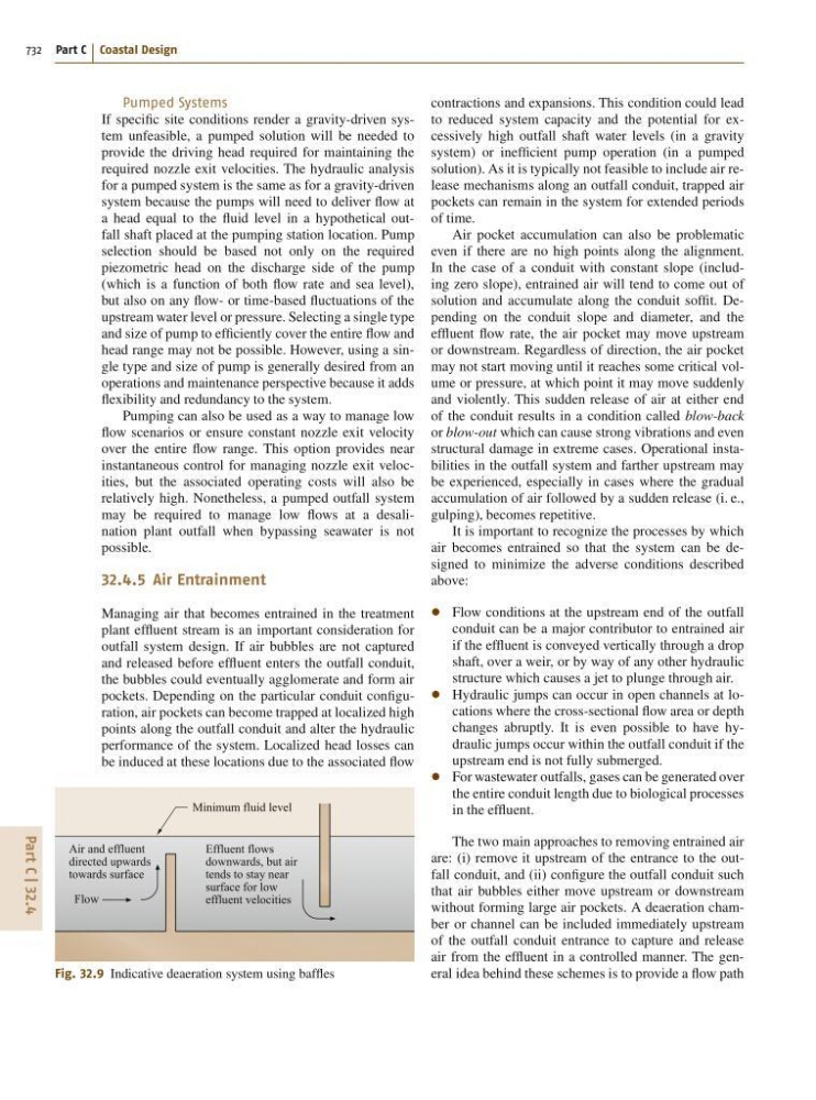
Fig. 32.9 Indicative deaeration system using baffles
contractions and expansions. This condition could lead
to reduced system capacity and the potential for excessively high outfall shaft water levels (in a gravity
system) or inefficient pump operation (in a pumped
solution). As it is typically not feasible to include air release mechanisms along an outfall conduit, trapped air
pockets can remain in the system for extended periods
of time.
Air pocket accumulation can also be problematic
even if there are no high points along the alignment.
In the case of a conduit with constant slope (including zero slope), entrained air will tend to come out of
solution and accumulate along the conduit soffit. Depending on the conduit slope and diameter, and the
effluent flow rate, the air pocket may move upstream
or downstream. Regardless of direction, the air pocket
may not start moving until it reaches some critical volume or pressure, at which point it may move suddenly
and violently. This sudden release of air at either end
of the conduit results in a condition called blow-back
or blow-out which can cause strong vibrations and even
structural damage in extreme cases. Operational instabilities in the outfall system and farther upstream may
be experienced, especially in cases where the gradual
accumulation of air followed by a sudden release (i. e.,
gulping), becomes repetitive.
It is important to recognize the processes by which
air becomes entrained so that the system can be designed to minimize the adverse conditions described
above:
Flow conditions at the upstream end of the outfall
conduit can be a major contributor to entrained air
if the effluent is conveyed vertically through a drop
shaft, over a weir, or by way of any other hydraulic
structure which causes a jet to plunge through air.
Hydraulic jumps can occur in open channels at locations where the cross-sectional flow area or depth
changes abruptly. It is even possible to have hydraulic jumps occur within the outfall conduit if the
upstream end is not fully submerged.
For wastewater outfalls, gases can be generated over
the entire conduit length due to biological processes
in the effluent.
The two main approaches to removing entrained air
are: (i) remove it upstream of the entrance to the outfall conduit, and (ii) configure the outfall conduit such
that air bubbles either move upstream or downstream
without forming large air pockets. A deaeration chamber or channel can be included immediately upstream
of the outfall conduit entrance to capture and release
air from the effluent in a controlled manner. The general idea behind these schemes is to provide a flow path