

Marine Outfalls 32.4 Hydraulic Analysis and Design 733
Part C | 32.4
of sufficient length such that air bubbles have enough
time to rise to the surface before entering the conduit.
Indicative air bubble terminal rise velocities are provided in Falvey [32.31] and Lauchlan et al. [32.32]. To
minimize the deaeration chamber or channel flow path
length, effluent velocities can be reduced by increasing
the cross-sectional flow area. Properly configured baffle walls can also be used to direct flow upward and
facilitate air removal through the fluid–air interface, or
to permit only the effluent at the bottom of a chamber
or channel to continue downstream toward the outfall
conduit; effluent near the invert is likely to have less
entrained air than that near the surface for low effluent
velocities. Refer to Fig. 32.9 that shows an indicative
deaeration system using a baffled configuration.
In other cases where site constraints limit the
amount of space available for upstream deaeration
schemes, or where a majority of entrained air is the
result of biological activity occurring in the outfall conduit, an alternative approach can be taken. The conduit
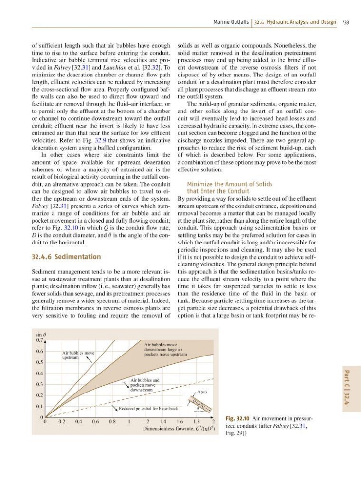
can be designed to allow air bubbles to travel to either the upstream or downstream ends of the system.
Falvey [32.31] presents a series of curves which summarize a range of conditions for air bubble and air
pocket movement in a closed and fully flowing conduit;
refer to Fig. 32.10 in which Q is the conduit flow rate,
D is the conduit diameter, and  is the angle of the conduit to the horizontal.
32.4.6 Sedimentation
Sediment management tends to be a more relevant issue at wastewater treatment plants than at desalination
plants; desalination inflow (i. e., seawater) generally has
fewer solids than sewage, and its pretreatment processes
generally remove a wider spectrum of material. Indeed,
the filtration membranes in reverse osmosis plants are
very sensitive to fouling and require the removal of
0
0.2
0.4
0.6
0.8
1
1.2
1.4
Air bubbles move
downstream large air
pockets move upstream
Air bubbles and
pockets move
downstream
D (m)
θ
Q ( m 3
/s )
Reduced potential for blow-back
Air bubbles move
upstream
1.6
1.8
2
sin θ
Dimensionless flowrate, Q
2 /(gD
5
)
0.7
0.6
0.5
0.4
0.3
0.2
0.1
0
Fig. 32.10 Air movement in pressurized conduits (after Falvey [32.31,
Fig. 29])
solids as well as organic compounds. Nonetheless, the
solid matter removed in the desalination pretreatment
processes may end up being added to the brine effluent downstream of the reverse osmosis filters if not
disposed of by other means. The design of an outfall
conduit for a desalination plant must therefore consider
all plant processes that discharge an effluent stream into
the outfall system.
The build-up of granular sediments, organic matter,
and other solids along the invert of an outfall conduit will eventually lead to increased head losses and
decreased hydraulic capacity. In extreme cases, the conduit section can become clogged and the function of the
discharge nozzles impeded. There are two general approaches to reduce the risk of sediment build-up, each
of which is described below. For some applications,
a combination of these options may prove to be the most
effective solution.
Minimize the Amount of Solids
that Enter the Conduit
By providing a way for solids to settle out of the effluent
stream upstream of the conduit entrance, deposition and
removal becomes a matter that can be managed locally
at the plant site, rather than along the entire length of the
conduit. This approach using sedimentation basins or
settling tanks may be the preferred solution for cases in
which the outfall conduit is long and/or inaccessible for
periodic inspections and cleaning. It may also be used
if it is not possible to design the conduit to achieve selfcleaning velocities. The general design principle behind
this approach is that the sedimentation basins/tanks reduce the effluent stream velocity to a point where the
time it takes for suspended particles to settle is less
than the residence time of the fluid in the basin or
tank. Because particle settling time increases as the target particle size decreases, a potential drawback of this
option is that a large basin or tank footprint may be re-