

Part C | 31.3
704 Part C Coastal Design
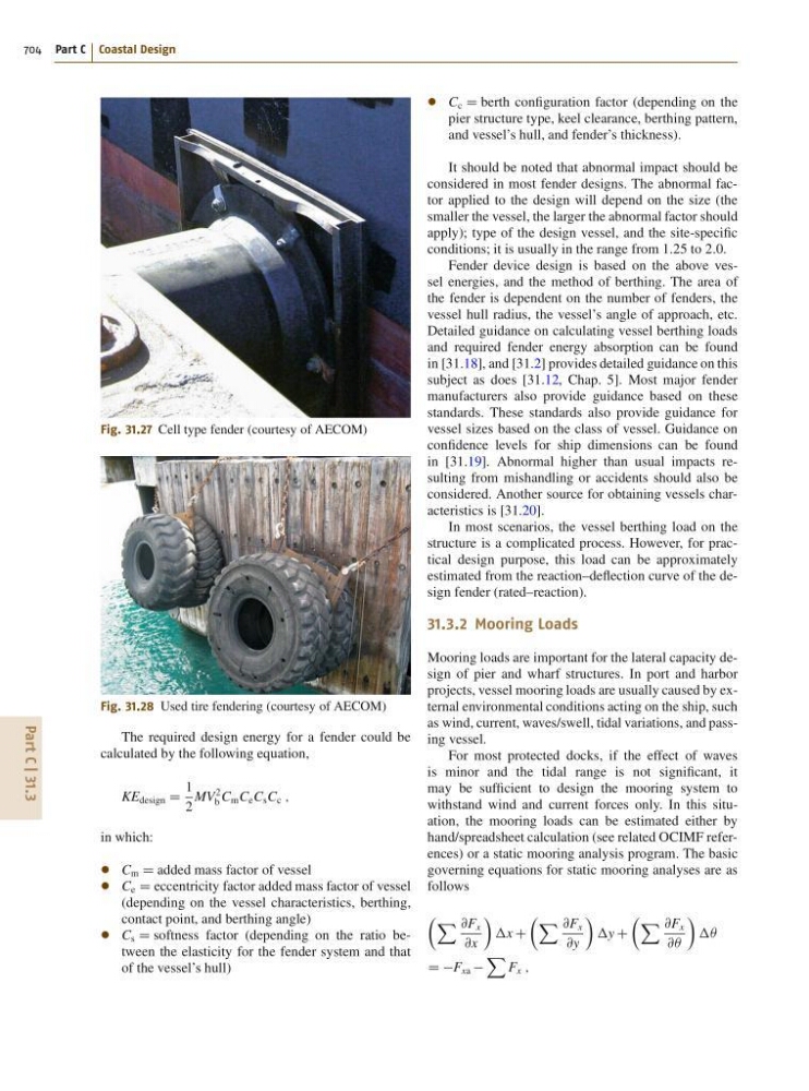
Fig. 31.27 Cell type fender (courtesy of AECOM)
Fig. 31.28 Used tire fendering (courtesy of AECOM)
The required design energy for a fender could be
calculated by the following equation,
KE design D
1
2
MV
2
b C m C e C s C c ;
in which:
C m D added mass factor of vessel
C e D eccentricity factor added mass factor of vessel
(depending on the vessel characteristics, berthing,
contact point, and berthing angle)
C s D softness factor (depending on the ratio between the elasticity for the fender system and that
of the vessel’s hull)
C c D berth configuration factor (depending on the
pier structure type, keel clearance, berthing pattern,
and vessel’s hull, and fender’s thickness).
It should be noted that abnormal impact should be
considered in most fender designs. The abnormal factor applied to the design will depend on the size (the
smaller the vessel, the larger the abnormal factor should
apply); type of the design vessel, and the site-specific
conditions; it is usually in the range from 1:25 to 2:0.
Fender device design is based on the above vessel energies, and the method of berthing. The area of
the fender is dependent on the number of fenders, the
vessel hull radius, the vessel’s angle of approach, etc.
Detailed guidance on calculating vessel berthing loads
and required fender energy absorption can be found
in [31.18], and [31.2] provides detailed guidance on this
subject as does [31.12, Chap. 5]. Most major fender
manufacturers also provide guidance based on these
standards. These standards also provide guidance for
vessel sizes based on the class of vessel. Guidance on
confidence levels for ship dimensions can be found
in [31.19]. Abnormal higher than usual impacts resulting from mishandling or accidents should also be
considered. Another source for obtaining vessels characteristics is [31.20].
In most scenarios, the vessel berthing load on the
structure is a complicated process. However, for practical design purpose, this load can be approximately
estimated from the reaction–deflection curve of the design fender (rated–reaction).
31.3.2 Mooring Loads
Mooring loads are important for the lateral capacity design of pier and wharf structures. In port and harbor
projects, vessel mooring loads are usually caused by external environmental conditions acting on the ship, such
as wind, current, waves/swell, tidal variations, and passing vessel.
For most protected docks, if the effect of waves
is minor and the tidal range is not significant, it
may be sufficient to design the mooring system to
withstand wind and current forces only. In this situation, the mooring loads can be estimated either by
hand/spreadsheet calculation (see related OCIMF references) or a static mooring analysis program. The basic
governing equations for static mooring analyses are as
follows
 X @F x
@x
Ã
x C
 X @F x
@y
Ã
y C
 X @F x
@Â
Ã
Â
D DF xa
X
F x ;