

Port and Harbor Design 31.3 Loads on Structures due to Vessel Mooring and Berthing 705
Part C | 31.3
 X @F y
@x
Ã
x C
 X @F y
@y
Ã
y C
 X @F y
@Â
Ã
Â
D DF ya
X
F y ;
 X @M xy
@x
Ã
x C
 X @M xy
@y
Ã
y C
 X @M xy
@Â
Ã
Â
D DM xa
X
M xy ;
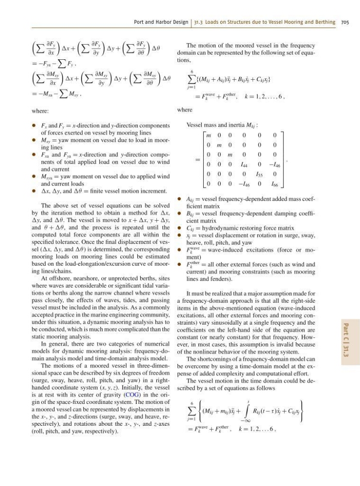
where:
F x and F y D x-direction and y-direction components
of forces exerted on vessel by mooring lines
M xy D yaw moment on vessel due to load in mooring lines
F xa and F ya D x-direction and y-direction components of total applied load on vessel due to wind
and current
M xya D yaw moment on vessel due to applied wind
and current loads
x, y, and  D finite vessel motion increment.
The above set of vessel equations can be solved
by the iteration method to obtain a method for x,
y, and  . The vessel is moved to x C x, y C y,
and  C  , and the process is repeated until the
computed total force components are all within the
specified tolerance. Once the final displacement of vessel (x, y, and  ) is determined, the corresponding
mooring loads on mooring lines could be estimated
based on the load-elongation/excursion curve of mooring lines/chains.
At offshore, nearshore, or unprotected berths, sites
where waves are considerable or significant tidal variations or berths along the narrow channel where vessels
pass closely, the effects of waves, tides, and passing
vessel must be included in the analysis. As a commonly
accepted practice in the marine engineering community,
under this situation, a dynamic mooring analysis has to
be conducted, which is much more complicated than the
static mooring analysis.
In general, there are two categories of numerical
models for dynamic mooring analysis: frequency-domain analysis model and time-domain analysis model.
The motions of a moored vessel in three-dimensional space can be described by six degrees of freedom
(surge, sway, heave, roll, pitch, and yaw) in a righthanded coordinate system (x; y; z). Initially, the vessel
is at rest with its center of gravity (COG) in the origin of the space-fixed coordinate system. The motion of
a moored vessel can be represented by displacements in
the x-, y-, and z-directions (surge, sway, and heave, respectively), and rotations about the x-, y-, and z-axes
(roll, pitch, and yaw, respectively).
The motion of the moored vessel in the frequency
domain can be represented by the following set of equations,
6
X
jD1
f.M kj C A kj / R
x j C B kj P
x j C C kj x j g
D F
wave
k
C F
other
k
; k D 1; 2; : : : ; 6 ;
where
Vessel mass and inertia M kj W
D
2
6
6
6
6
6
6
6
6
6
4
m 0 0
0
0
0
0 m 0
0
0
0
0 0 m
0
0
0
0 0 0 I 44
0 I 46
0 0 0
0
I 55
0
0 0 0 I 46 0
I 66
3
7
7
7
7
7
7
7
7
7
5
:
A kj D vessel frequency-dependent added mass coefficient matrix
B kj D vessel frequency-dependent damping coefficient matrix
C kj D hydrodynamic restoring force matrix
x j D vessel displacement or rotation in surge, sway,
heave, roll, pitch, and yaw
F
wave
k
D wave-induced excitations (force or moment)
F
other
k
D all other external forces (such as wind and
current) and mooring constraints (such as mooring
lines and fenders).
It must be realized that a major assumption made for
a frequency-domain approach is that all the right-side
items in the above-mentioned equation (wave-induced
excitations, all other external forces and mooring constraints) vary sinusoidally at a single frequency and the
coefficients on the left-hand side of the equation are
constant (or nearly constant) for that frequency. However, in most cases, this assumption is invalid because
of the nonlinear behavior of the mooring system.
The shortcomings of a frequency-domain model can
be overcome by using a time-domain model at the expense of added complexity and computational effort.
The vessel motion in the time domain could be described by a set of equations as follows
6
X
jD1
8
<
:
.M kj C m kj / R
x j C
t
Z
1
R kj .t / P
x j C C kj x j
9
=
;
D F
wave
k
C F
other
k
; k D 1; 2; : : : 6 ;