

Port and Harbor Design 31.3 Loads on Structures due to Vessel Mooring and Berthing 703
Part C | 31.3
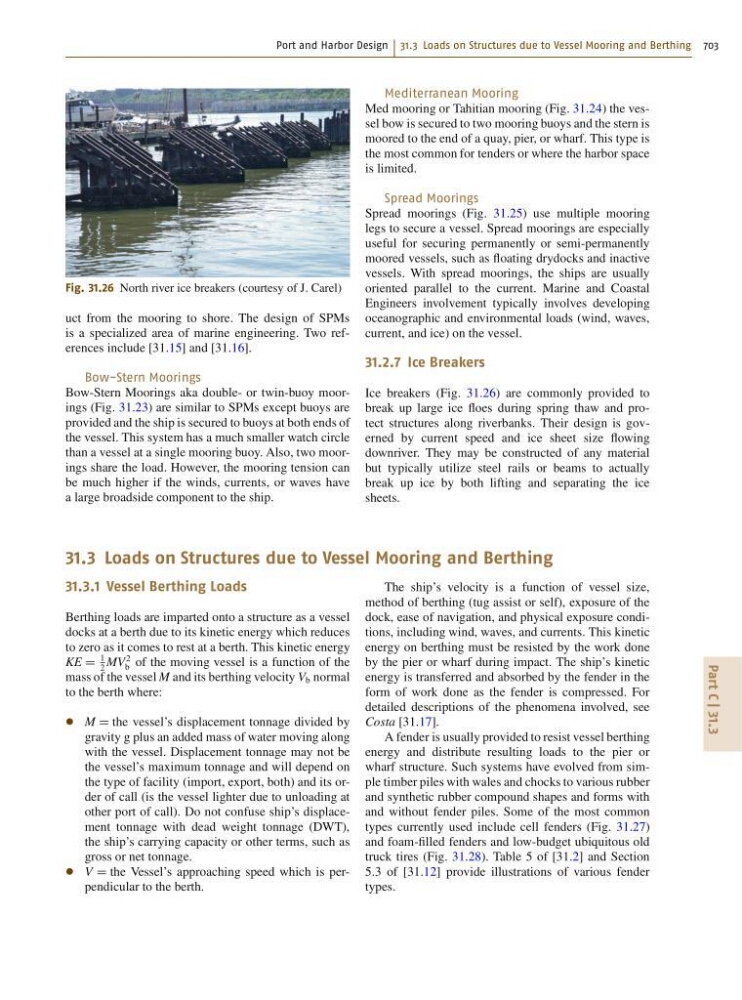
Fig. 31.26 North river ice breakers (courtesy of J. Carel)
uct from the mooring to shore. The design of SPMs
is a specialized area of marine engineering. Two references include [31.15] and [31.16].
Bow-Stern Moorings
Bow-Stern Moorings aka double- or twin-buoy moorings (Fig. 31.23) are similar to SPMs except buoys are
provided and the ship is secured to buoys at both ends of
the vessel. This system has a much smaller watch circle
than a vessel at a single mooring buoy. Also, two moorings share the load. However, the mooring tension can
be much higher if the winds, currents, or waves have
a large broadside component to the ship.
Mediterranean Mooring
Med mooring or Tahitian mooring (Fig. 31.24) the vessel bow is secured to two mooring buoys and the stern is
moored to the end of a quay, pier, or wharf. This type is
the most common for tenders or where the harbor space
is limited.
Spread Moorings
Spread moorings (Fig. 31.25) use multiple mooring
legs to secure a vessel. Spread moorings are especially
useful for securing permanently or semi-permanently
moored vessels, such as floating drydocks and inactive
vessels. With spread moorings, the ships are usually
oriented parallel to the current. Marine and Coastal
Engineers involvement typically involves developing
oceanographic and environmental loads (wind, waves,
current, and ice) on the vessel.
31.2.7 Ice Breakers
Ice breakers (Fig. 31.26) are commonly provided to
break up large ice floes during spring thaw and protect structures along riverbanks. Their design is governed by current speed and ice sheet size flowing
downriver. They may be constructed of any material
but typically utilize steel rails or beams to actually
break up ice by both lifting and separating the ice
sheets.
31.3 Loads on Structures due to Vessel Mooring and Berthing
31.3.1 Vessel Berthing Loads
Berthing loads are imparted onto a structure as a vessel
docks at a berth due to its kinetic energy which reduces
to zero as it comes to rest at a berth. This kinetic energy
KE D
1
2
MV
2
b of the moving vessel is a function of the
mass of the vessel M and its berthing velocity V b normal
to the berth where:
M D the vessel’s displacement tonnage divided by
gravity g plus an added mass of water moving along
with the vessel. Displacement tonnage may not be
the vessel’s maximum tonnage and will depend on
the type of facility (import, export, both) and its order of call (is the vessel lighter due to unloading at
other port of call). Do not confuse ship’s displacement tonnage with dead weight tonnage (DWT),
the ship’s carrying capacity or other terms, such as
gross or net tonnage.
V D the Vessel’s approaching speed which is perpendicular to the berth.
The ship’s velocity is a function of vessel size,
method of berthing (tug assist or self), exposure of the
dock, ease of navigation, and physical exposure conditions, including wind, waves, and currents. This kinetic
energy on berthing must be resisted by the work done
by the pier or wharf during impact. The ship’s kinetic
energy is transferred and absorbed by the fender in the
form of work done as the fender is compressed. For
detailed descriptions of the phenomena involved, see
Costa [31.17].
A fender is usually provided to resist vessel berthing
energy and distribute resulting loads to the pier or
wharf structure. Such systems have evolved from simple timber piles with wales and chocks to various rubber
and synthetic rubber compound shapes and forms with
and without fender piles. Some of the most common
types currently used include cell fenders (Fig. 31.27)
and foam-filled fenders and low-budget ubiquitous old
truck tires (Fig. 31.28). Table 5 of [31.2] and Section
5.3 of [31.12] provide illustrations of various fender
types.