

Storm Hazard Mitigation Structures 30.3 Shoreline Stabilization Structures 677
Part C | 30.3
The key geometric variables are the structure length
L s and the distance offshore Y from the renourished
beach at the design beach width. Dally and Pope [30.75]
recommend L s =Y D 0:5 to 0:67 for the shore system
and even further offshore (i. e., L s =Y D 0:125) for very
long systems of near-shore breakwaters as for example
constructed at Presque Isle, Pennsylvania, USA.
A detached, near-shore breakwater system with
salient formation is the preferred, breakwater shoreline stabilization system recommended by the US Army
Corps of Engineers as stated in [30.1]. This design
permits long-shore sediment transport to continue to
move through and past the project area to down drift
shorelines and minimize down drift impacts. Wave
action and long-shore currents are strong enough to
keep the salient from connecting to the structure.
An extensive literature review of both near-shore and
headland- breakwater systems can be found in Chasten
et al. [30.82] as applied on micro-tidal beaches.
Note in Fig. 30.23 that the salient distances from
the design beach width shoreline position, W, are not
symmetrical (Y s ¤ Y g ) and that the storm erosion distance, e in the gap must be included to predict Y min
for the design storm. The plan form configuration of
the salient-shaped beach, and the storm erosion distance, e have been studied extensively over the years,
but no general analytical procedure exists. See Chasten
et al. [30.82] for some examples. The breakwater crest
elevation and crest width, the structure permeability,
the structure slope, and other factors also influence the
functional performance of near-shore breakwater systems. For these reasons, numerical models of waves,
wave-induced currents, sediment transport, and bathymetric change have been employed to study the shoreline modifications created by near-shore breakwater
systems.
On coasts with tides in the range of 24 m (mesotidal) or greater than 4 m (macro-tidal), design guidance is limited. Because over 75% of the UK coastline is classified as meso- or macro-tidal, Rodgers
et al. [30.83] concluded that the UK needed to study
and develop guidelines for breakwater performance
on sandy, macro-tidal coasts. Two morphological, numerical models were employed (PISCES and MIKE
21-CAMS) in the effort with conflicting results as reported in Environmental Agency [30.84]. This is not
surprising since the numerical models require four coupled, submodules (waves, currents, sediment transport,
and bathymetric change) and use different empirical
formulations for sediment transport. In fact, the design
guidelines cited above for micro-tidal coasts have been
used to confirm numerical model results [30.85].
However, results of the numerical modeling study
did reveal some important differences that have been
Upcoast
fixed point
Shoreline
(parabolic form)
R
Co nt ro l lin e R o
θ
β = 24°
W av e cr es t
Downcoast
fixed point
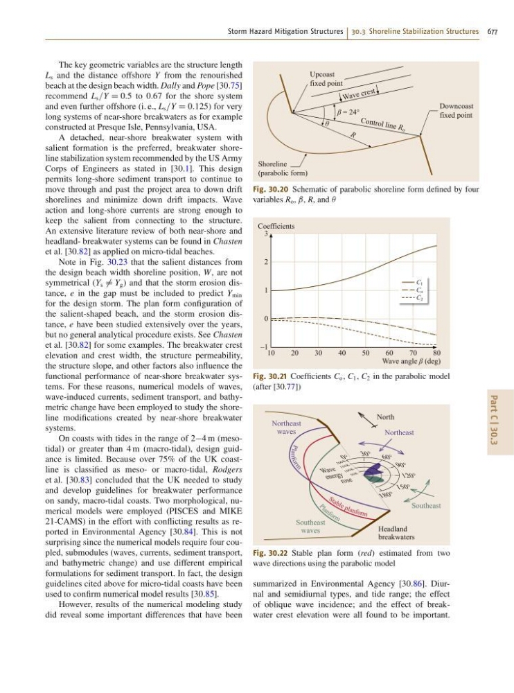
Fig. 30.20 Schematic of parabolic shoreline form defined by four
variables R o , ˇ, R, and Â
C 1
C o
C 2
10
20
30
40
50
60
70
80
Coefficients
Wave angle β (deg)
3
2
1
0
–1
Fig. 30.21 Coefficients C o , C 1 , C 2 in the parabolic model
(after [30.77])
P
la
nfo
r
m
P
l
a n f o r m
S t a b le p la n fo rm
18 0°
150°
120°
90°
60°
30°
0°
20 0K
15 0K
10 0K
50 K
Headland
breakwaters
Northeast
waves
Northeast
North
Southeast
waves
Southeast
W av e
en erg y
ros e
Fig. 30.22 Stable plan form (red) estimated from two
wave directions using the parabolic model
summarized in Environmental Agency [30.86]. Diurnal and semidiurnal types, and tide range; the effect
of oblique wave incidence; and the effect of breakwater crest elevation were all found to be important.