

Part C | 30.3
678 Part C Coastal Design
Nourished (MHW) shoreline
MHW shoreline
(dominant)
Q offshore
Q net
Q gross
Salient
Y min (MHW) (Design storm)
W
Design beach
width
Breaker
line
(nominal)
Original shoreline (MHW)
Original shoreline (MHW)
MHW
MLW
MTL
Base (reference) line
Nearshore
breakwater
Base
(reference)
line
Protected
uplands
(cliffs, dunes,
man′s
artifacts)
(Vegetation
line)
Design beach
width W
Y min (MHW)
design storm
e
Berm
Berm
Original profile
Profile in gap
Profile behind breakwater
Waves (dominant) (H o , H b ) T, Θ
a)
b)
H b
Gap
C L
C L
C L
L s
L g
Y s
Y s
d s
Y
Y g
d 50
Y Y b
Y g
e
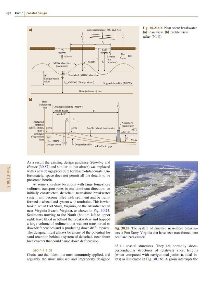
Fig. 30.23a,b Near-shore breakwater.
(a) Plan view, (b) profile view
(after [30.1])
As a result the existing design guidance (Fleming and
Hamer [30.87] and similar to that above) was replaced
with a new design procedure for macro-tidal coasts. Unfortunately, space does not permit all the details to be
presented herein.
At some shoreline locations with large long-shore
sediment transport rates in one dominant direction, an
initially constructed, detached, near-shore breakwater
system will become filled with sediment and be transformed to a headland system with tombolos. This is what
took place at Fort Story, Virginia, on the Atlantic Ocean
near Virginia Beach, Virginia, as shown in Fig. 30.24.
Sediments moving to the North (bottom left to upper
right) have filled in behind the breakwaters and trapped
a large volume of sediment that was not transported to
downdrift beaches and is producing down drift impacts.
The designer must always be aware of the potential for
sand retention behind a system of detached, near-shore
breakwaters that could cause down drift erosion.
Groin Fields
Groins are the oldest, the most commonly applied, and
arguably the most misused and improperly designed
Fig. 30.24 The system of nineteen near-shore breakwaters at Fort Story, Virginia that have been transformed into
headland breakwaters
of all coastal structures. They are normally shoreperpendicular structures of relatively short lengths
(when compared with navigational jetties at tidal inlets) as illustrated in Fig. 30.16e. A groin interrupts the