

Storm Hazard Mitigation Structures 30.2 Coastal Armoring Structures 663
Part C | 30.2
30.2.3 Structural Design
The structural design of coastal armoring structures involves the water levels and wave forces (and possibly
ice loads) that may produce movements (sliding, rotation, overturning, etc.) of complete sections of the
structure or loss of stability for individual units of
rock (rubble)- and concrete-armor layers of the structure. Structural stability is the goal under design storm
events. Damage is probable under more extreme storm
conditions for the given design constraints (economic,
environmental, etc.) so that maintenance costs for repair must always be considered in the initial design
phase of the project. We herein consider, monolithic,
caisson-type, vertical-walled structures and rock (rubble) revetments. Water level and wave loads on vertical
seawalls are similar as considered herein for caissons.
The stability of rubble-mound (rock) breakwaters is
also included here with further discussion in Sect. 30.3.
The origin of the use of the word rubble for rock structures is unknown.
The choice between use of a vertical-walled,
caisson-type structure or a rubble-mound breakwater
depends on many factors with water depth being one of
the most important. In deep water, the cross-sectional
area (hence cost) of the caisson-type is lowest where
as in shallow water the material cost often favors the
rubble-mound type. No general design rules apply so
that both types should be considered in the feasibility
study.
Oumeraci et al. [30.5] cite the following reasons
for research on monolithic, caisson-type structures:
catastrophic failures in Europe, need for breakwaters
at greater depths, need for environmentally friendly
structures, need for multipurpose structures, and the potential for application in sea-wall designs. The result
was the PROVERBS project as discussed below.
Vertical-Walled, Caisson-Type Structures
With no waves present, the water pressure distribution
on a vertical wall is hydrostatic being zero at the surface and z at any distance z below the surface (Cz
is positive above the surface). The mass density of the
fluid is . The horizontal, water force per unit width f h
on the vertical wall is then
1
2
gh
2 , where h is the fluid
water depth at the wall. Storms increase the water depth
and bring waves that are both reflected by and break on
the wall to greatly increase the horizontal forces on the
wall. A long history of research efforts throughout the
world has produced many formulas over the years for
the calculation of wave pressures and forces on vertical
walls.
Pioneering efforts of Japanese coastal engineers
have led the way to develop practical formulas for the
wave pressures and forces on caisson-type structures
under both nonbreaking and breaking wave conditions.
We focus on these herein.
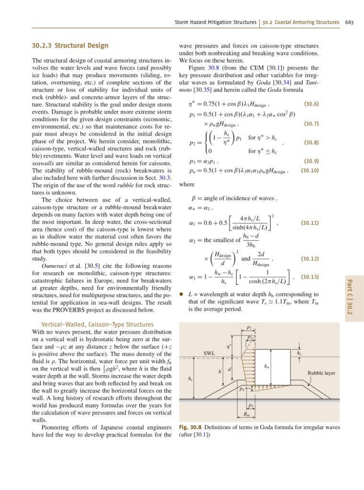
Figure 30.8 (from the CEM [30.1]) presents the
key pressure distribution and other variables for irregular waves as formulated by Goda [30.34] and Tanimoto [30.35] and herein called the Goda formula
Á
D 0:75.1 C cos ˇ// 1 H design ;
(30.6)
p 1 D 0:5.1 C cos ˇ/.. 1 ˛ 1 C 2 ˛ cos
2
ˇ/
w gH design ;
(30.7)
p 2 D
8
<
:
Â
1
h c
Á
Ã
p 1 for Á
> h c
0
f o r Á
Ä h c
;
(30.8)
p 3 D ˛ 3 p 1 ;
(30.9)
p u D 0:5.1 C cos ˇ// 3 ˛ 1 ˛ 3 w gH design ;
(30.10)
where
ˇ D angle of incidence of waves ;
˛ D ˛ 2 ;
˛ 1 D 0:6 C 0:5
Ä 4h s =L
sinh.4h s =L/
2
;
(30.11)
˛ 2 D the smallest of
h b d
3h b
 H design
d
à 2
and
2d
H design
;
(30.12)
˛ 3 D 1
h w h c
h s
Ä
1
1
cosh .2h s =L/
; (30.13)
L = wavelength at water depth h b corresponding to
that of the significant wave T s ' 1:1T m , where T m
is the average period.
B m
p 3
p u
p 1
p 2
η *
h w
h
'
d
h s
h c
SWL
Rubble layer
Fig. 30.8 Definitions of terms in Goda formula for irregular waves
(after [30.1])