

Part C | 30.2
664 Part C Coastal Design
h b = water depth at a distance of 5 H s seaward of the
breakwater front wall.
1 , 2 , and 3 are the modification factors depending on the structure type. For conventional vertical
wall structures, 1 D 2 D 3 D 1. Values for other
structure types are given in related tables.
The key pressure is p 1 at the design still wave level
(SWL) and its calculation depends on many factors in
the formulation listed above including the design wave
height H design . What to use for the design wave height in
the Goda formula to calculate p 1 is subject to debate as
discussed further below. The water level on the leeward
side of the structure is the same so that the hydrostatic
forces on the structure are balanced out and not shown.
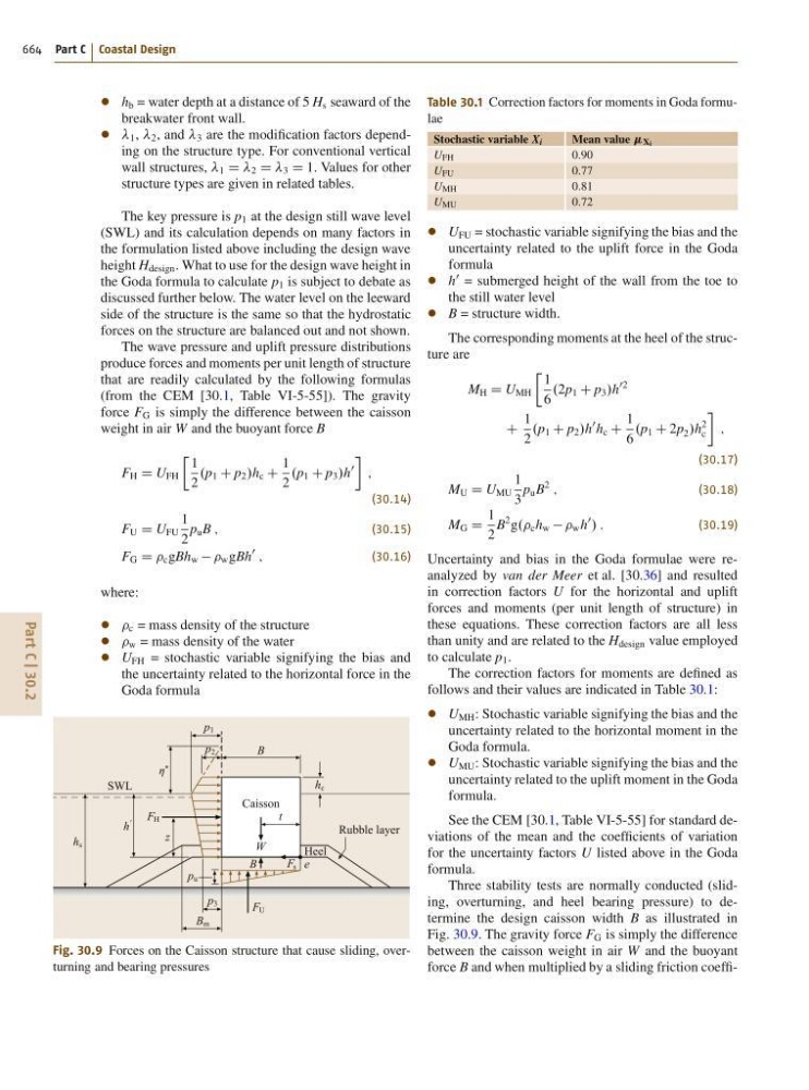
The wave pressure and uplift pressure distributions
produce forces and moments per unit length of structure
that are readily calculated by the following formulas
(from the CEM [30.1, Table VI-5-55]). The gravity
force F G is simply the difference between the caisson
weight in air W and the buoyant force B
F H D U FH
Ä 1
2
.p 1 C p 2 /h c C
1
2
.p 1 C p 3 /h
0
;
(30.14)
F U D U FU
1
2
p u B ;
(30.15)
F G D c gBh w w gBh
0
;
(30.16)
where:
c = mass density of the structure
w = mass density of the water
U FH = stochastic variable signifying the bias and
the uncertainty related to the horizontal force in the
Goda formula
B m
p 3
F s
F U
F H
B
p u
p 1
p 2
η *
t
B
W
h
'
z
h s
h c
SWL
Rubble layer
Heel
e
Caisson
Fig. 30.9 Forces on the Caisson structure that cause sliding, overturning and bearing pressures
Table 30.1 Correction factors for moments in Goda formulae
Stochastic variable X i
Mean value Xi
U FH
0:90
U FU
0:77
U MH
0:81
U MU
0:72
U FU = stochastic variable signifying the bias and the
uncertainty related to the uplift force in the Goda
formula
h
0 = submerged height of the wall from the toe to
the still water level
B = structure width.
The corresponding moments at the heel of the structure are
M H D U MH
Ä 1
6
.2p 1 C p 3 /h
02
C
1
2
.p 1 C p 2 /h
0 h c C
1
6
.p 1 C 2p 2 /h
2
c
;
(30.17)
M U D U MU
1
3
p u B
2
;
(30.18)
M G D
1
2
B
2 g.. c h w w h
0
/ :
(30.19)
Uncertainty and bias in the Goda formulae were reanalyzed by van der Meer et al. [30.36] and resulted
in correction factors U for the horizontal and uplift
forces and moments (per unit length of structure) in
these equations. These correction factors are all less
than unity and are related to the H design value employed
to calculate p 1 .
The correction factors for moments are defined as
follows and their values are indicated in Table 30.1:
U MH : Stochastic variable signifying the bias and the
uncertainty related to the horizontal moment in the
Goda formula.
U MU : Stochastic variable signifying the bias and the
uncertainty related to the uplift moment in the Goda
formula.
See the CEM [30.1, Table VI-5-55] for standard deviations of the mean and the coefficients of variation
for the uncertainty factors U listed above in the Goda
formula.
Three stability tests are normally conducted (sliding, overturning, and heel bearing pressure) to determine the design caisson width B as illustrated in
Fig. 30.9. The gravity force F G is simply the difference
between the caisson weight in air W and the buoyant
force B and when multiplied by a sliding friction coeffi-