

Part C | 30.2
660 Part C Coastal Design
c) Quarrystone
Field stone
Concrete
Bags
Gabions
Vegetations
Concrete armor
units
Concrete revetment
blocks
Concrete-filled
mattress
Concrete slabs
Landing mat
Randomly–or
specially-placed
armor units
such as tribars,
dolosse, etc.
Underlayer
Filter
Filter-layer
Filter
Filter
Filter
Filter
Anchor
Landing mat
Filter
Uniform-zized
armor stone or
graded riprap
Large, rounded
field stone
armor
Cast in place
concrete slab
on grade
Sand or
concrete fill in
fabric bags
Concrete
revetment
blocks
Concrete-filled
mattress
Concrete slabs
from demolition
work
Rock-filled
gabion baskets
Beach and upland
species above the
intertidal zone
Marsh species in
the intertidal zone
MHW
MLW
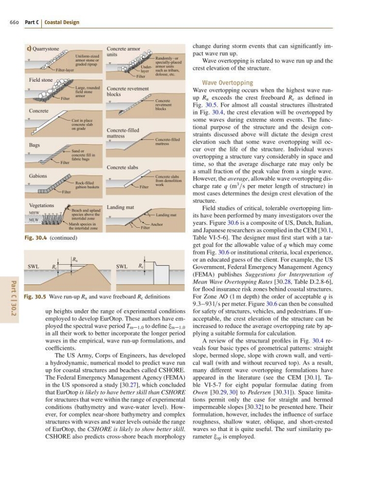
Fig. 30.4 (continued)
SWL
R c
SWL
R c
R u
Fig. 30.5 Wave run-up R u and wave freeboard R c definitions
up heights under the range of experimental conditions
employed to develop EurOtop. These authors have employed the spectral wave period T m1:0 to define m1:0
in all their work to better incorporate the longer period
waves in the empirical, wave run-up formulations, and
coefficients.
The US Army, Corps of Engineers, has developed
a hydrodynamic, numerical model to predict wave run
up for coastal structures and beaches called CSHORE.
The Federal Emergency Management Agency (FEMA)
in the US sponsored a study [30.27], which concluded
that EurOtop is likely to have better skill than CSHORE
for structures that were within the range of experimental
conditions (bathymetry and wave-water level). However, for complex near-shore bathymetry and complex
structures with waves and water levels outside the range
of EurOtop, the CSHORE is likely to show better skill.
CSHORE also predicts cross-shore beach morphology
change during storm events that can significantly impact wave run up.
Wave overtopping is related to wave run up and the
crest elevation of the structure.
Wave Overtopping
Wave overtopping occurs when the highest wave runup R u exceeds the crest freeboard R c as defined in
Fig. 30.5. For almost all coastal structures illustrated
in Fig. 30.4, the crest elevation will be overtopped by
some waves during extreme storm events. The functional purpose of the structure and the design constraints discussed above will dictate the design crest
elevation such that some wave overtopping will occur over the life of the structure. Individual waves
overtopping a structure vary considerably in space and
time, so that the average discharge rate may only be
a small fraction of the peak value from a single wave.
However, the average, allowable wave overtopping discharge rate q (m
3
=s per meter length of structure) in
most cases determines the design crest elevation of the
structure.
Field studies of critical, tolerable overtopping limits have been performed by many investigators over the
years. Figure 30.6 is a composite of US, Dutch, Italian,
and Japanese researchers as complied in the CEM [30.1,
Table VI-5-6]. The designer must first start with a target goal for the allowable value of q which may come
from Fig. 30.6 or institutional criteria, local experience,
or an educated guess of the client. For example, the US
Government, Federal Emergency Management Agency
(FEMA) publishes Suggestions for Interpretation of
Mean Wave Overtopping Rates [30.28, Table D.2.8-6],
for flood insurance risk zones behind coastal structures.
For Zone AO (1 m depth) the order of acceptable q is
9:393 l=s per meter. Figure 30.6 can then be consulted
for safety of structures, vehicles, and pedestrians. If unacceptable, the crest elevation of the structure can be
increased to reduce the average overtopping rate by applying a suitable formula for calculation.
A review of the structural profiles in Fig. 30.4 reveals four basic types of geometrical patterns: straight
slope, bermed slope, slope with crown wall, and vertical wall (with and without recurved top). As a result,
many different wave overtopping formulations have
appeared in the literature (see the CEM [30.1], Table VI-5-7 for eight popular formulae dating from
Owen [30.29, 30] to Pedersen [30.31]). Space limitations permit only the case for straight and bermed
impermeable slopes [30.32] to be presented here. Their
formulation, however, includes the influence of surface
roughness, shallow water, oblique, and short-crested
waves so that it is quite useful. The surf similarity parameter op is employed.