

Part B | 13.4
334 Part B Autonomous Ocean Vehicles, Subsystems and Control
Conventional
Original
Optimized
0
2000
4000
6000
8000
10 000 12 000 14 000
ObjHigh
Design ID
1.2
1.1
1
0.9
0.8
0.7
0.6
0.5
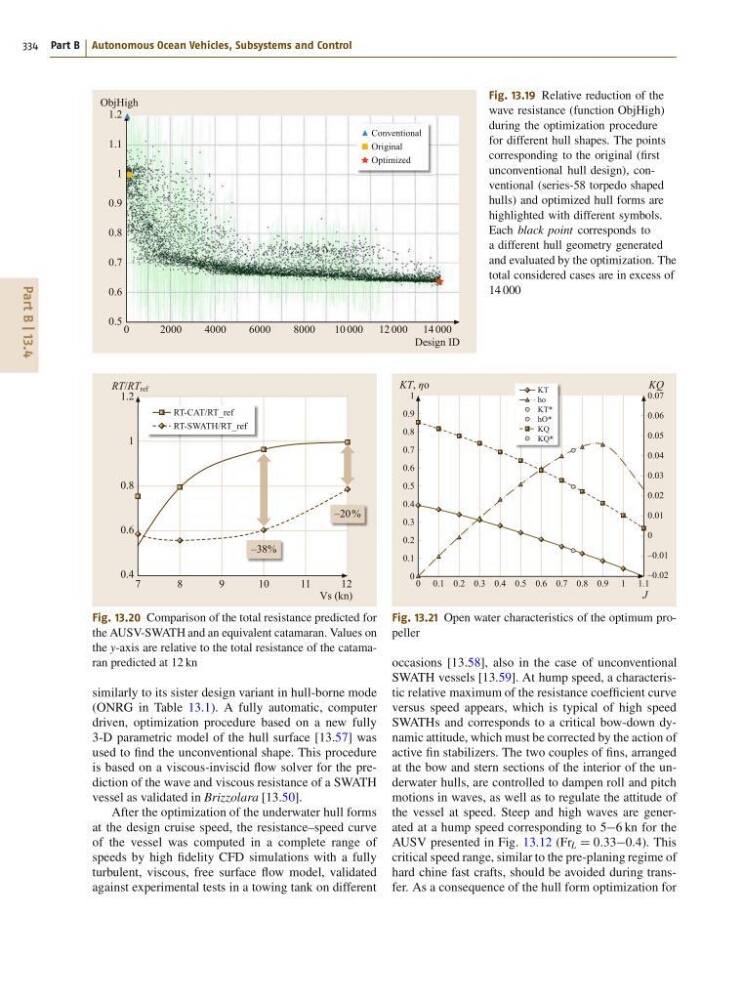
Fig. 13.19 Relative reduction of the
wave resistance (function ObjHigh)
during the optimization procedure
for different hull shapes. The points
corresponding to the original (first
unconventional hull design), conventional (series-58 torpedo shaped
hulls) and optimized hull forms are
highlighted with different symbols.
Each black point corresponds to
a different hull geometry generated
and evaluated by the optimization. The
total considered cases are in excess of
14 000
RT-CAT/RT_ref
RT-SWATH/RT_ref
7
8
9
10
11
12
–20 %
–38%
RT/RT ref
Vs (kn)
1.2
1
0.8
0.6
0.4
Fig. 13.20 Comparison of the total resistance predicted for
the AUSV-SWATH and an equivalent catamaran. Values on
the y-axis are relative to the total resistance of the catamaran predicted at 12 kn
similarly to its sister design variant in hull-borne mode
(ONRG in Table 13.1). A fully automatic, computer
driven, optimization procedure based on a new fully
3-D parametric model of the hull surface [13.57] was
used to find the unconventional shape. This procedure
is based on a viscous-inviscid flow solver for the prediction of the wave and viscous resistance of a SWATH
vessel as validated in Brizzolara [13.50].
After the optimization of the underwater hull forms
at the design cruise speed, the resistance–speed curve
of the vessel was computed in a complete range of
speeds by high fidelity CFD simulations with a fully
turbulent, viscous, free surface flow model, validated
against experimental tests in a towing tank on different
KT
ho
KT*
hO*
KQ
KQ*
0 0.1 0.2 0.3 0.4 0.5 0.6 0.7 0.8 0.9 1 1.1
KT, ηo
KQ
J
1
0.9
0.8
0.7
0.6
0.5
0.4
0.3
0.2
0.1
0
0.07
0.06
0.05
0.04
0.03
0.02
0.01
0
–0.01
–0.02
Fig. 13.21 Open water characteristics of the optimum propeller
occasions [13.58], also in the case of unconventional
SWATH vessels [13.59]. At hump speed, a characteristic relative maximum of the resistance coefficient curve
versus speed appears, which is typical of high speed
SWATHs and corresponds to a critical bow-down dynamic attitude, which must be corrected by the action of
active fin stabilizers. The two couples of fins, arranged
at the bow and stern sections of the interior of the underwater hulls, are controlled to dampen roll and pitch
motions in waves, as well as to regulate the attitude of
the vessel at speed. Steep and high waves are generated at a hump speed corresponding to 56 kn for the
AUSV presented in Fig. 13.12 (Fr L D 0:330:4). This
critical speed range, similar to the pre-planing regime of
hard chine fast crafts, should be avoided during transfer. As a consequence of the hull form optimization for
334 Part B Autonomous Ocean Vehicles, Subsystems and Control
Conventional
Original
Optimized
0
2000
4000
6000
8000
10 000 12 000 14 000
ObjHigh
Design ID
1.2
1.1
1
0.9
0.8
0.7
0.6
0.5
Fig. 13.19 Relative reduction of the
wave resistance (function ObjHigh)
during the optimization procedure
for different hull shapes. The points
corresponding to the original (first
unconventional hull design), conventional (series-58 torpedo shaped
hulls) and optimized hull forms are
highlighted with different symbols.
Each black point corresponds to
a different hull geometry generated
and evaluated by the optimization. The
total considered cases are in excess of
14 000
RT-CAT/RT_ref
RT-SWATH/RT_ref
7
8
9
10
11
12
–20 %
–38%
RT/RT ref
Vs (kn)
1.2
1
0.8
0.6
0.4
Fig. 13.20 Comparison of the total resistance predicted for
the AUSV-SWATH and an equivalent catamaran. Values on
the y-axis are relative to the total resistance of the catamaran predicted at 12 kn
similarly to its sister design variant in hull-borne mode
(ONRG in Table 13.1). A fully automatic, computer
driven, optimization procedure based on a new fully
3-D parametric model of the hull surface [13.57] was
used to find the unconventional shape. This procedure
is based on a viscous-inviscid flow solver for the prediction of the wave and viscous resistance of a SWATH
vessel as validated in Brizzolara [13.50].
After the optimization of the underwater hull forms
at the design cruise speed, the resistance–speed curve
of the vessel was computed in a complete range of
speeds by high fidelity CFD simulations with a fully
turbulent, viscous, free surface flow model, validated
against experimental tests in a towing tank on different
KT
ho
KT*
hO*
KQ
KQ*
0 0.1 0.2 0.3 0.4 0.5 0.6 0.7 0.8 0.9 1 1.1
KT, ηo
KQ
J
1
0.9
0.8
0.7
0.6
0.5
0.4
0.3
0.2
0.1
0
0.07
0.06
0.05
0.04
0.03
0.02
0.01
0
–0.01
–0.02
Fig. 13.21 Open water characteristics of the optimum propeller
occasions [13.58], also in the case of unconventional
SWATH vessels [13.59]. At hump speed, a characteristic relative maximum of the resistance coefficient curve
versus speed appears, which is typical of high speed
SWATHs and corresponds to a critical bow-down dynamic attitude, which must be corrected by the action of
active fin stabilizers. The two couples of fins, arranged
at the bow and stern sections of the interior of the underwater hulls, are controlled to dampen roll and pitch
motions in waves, as well as to regulate the attitude of
the vessel at speed. Steep and high waves are generated at a hump speed corresponding to 56 kn for the
AUSV presented in Fig. 13.12 (Fr L D 0:330:4). This
critical speed range, similar to the pre-planing regime of
hard chine fast crafts, should be avoided during transfer. As a consequence of the hull form optimization for