

Autonomous Sea Surface Vehicles 13.4 Optimized Class of Autonomous Unmanned Surface Vehicles 333
Part B | 13.4
Hm
Mod 5
Mod 5b
Mod 5c_VCG corr
0
10
20
30
40
Heel 10°
Wind heeling moment
at 50 kn
7° Best angle of equilibrium
Righting moments for
different models
Heel 5°
Heel 15°
50
60
70
80
90
Righting moments (kNm)
Angle (deg)
60
40
20
0
–20
–40
–60
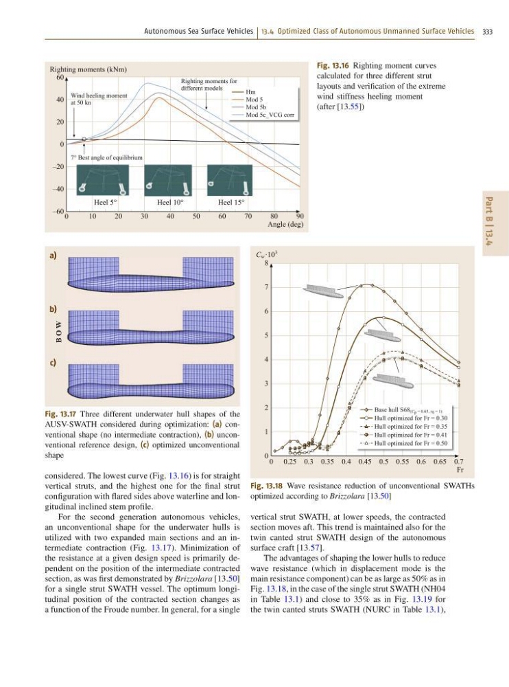
Fig. 13.16 Righting moment curves
calculated for three different strut
layouts and verification of the extreme
wind stiffness heeling moment
(after [13.55])
a)
b)
c)
B O W
Fig. 13.17 Three different underwater hull shapes of the
AUSV-SWATH considered during optimization: (a) conventional shape (no intermediate contraction), (b) unconventional reference design, (c) optimized unconventional
shape
considered. The lowest curve (Fig. 13.16) is for straight
vertical struts, and the highest one for the final strut
configuration with flared sides above waterline and longitudinal inclined stem profile.
For the second generation autonomous vehicles,
an unconventional shape for the underwater hulls is
utilized with two expanded main sections and an intermediate contraction (Fig. 13.17). Minimization of
the resistance at a given design speed is primarily dependent on the position of the intermediate contracted
section, as was first demonstrated by Brizzolara [13.50]
for a single strut SWATH vessel. The optimum longitudinal position of the contracted section changes as
a function of the Froude number. In general, for a single
Base hull S68 (C p = 0.65, r 0 = 1)
Hull optimized for Fr = 0.30
Hull optimized for Fr = 0.35
Hull optimized for Fr = 0.41
Hull optimized for Fr = 0.50
0 0.25 0.3 0.35 0.4 0.45 0.5 0.55 0.6 0.65 0.7
C w ·10
3
Fr
8
7
6
5
4
3
2
1
0
Fig. 13.18 Wave resistance reduction of unconventional SWATHs
optimized according to Brizzolara [13.50]
vertical strut SWATH, at lower speeds, the contracted
section moves aft. This trend is maintained also for the
twin canted strut SWATH design of the autonomous
surface craft [13.57].
The advantages of shaping the lower hulls to reduce
wave resistance (which in displacement mode is the
main resistance component) can be as large as 50% as in
Fig. 13.18, in the case of the single strut SWATH (NH04
in Table 13.1) and close to 35% as in Fig. 13.19 for
the twin canted struts SWATH (NURC in Table 13.1),
Part B | 13.4
Hm
Mod 5
Mod 5b
Mod 5c_VCG corr
0
10
20
30
40
Heel 10°
Wind heeling moment
at 50 kn
7° Best angle of equilibrium
Righting moments for
different models
Heel 5°
Heel 15°
50
60
70
80
90
Righting moments (kNm)
Angle (deg)
60
40
20
0
–20
–40
–60
Fig. 13.16 Righting moment curves
calculated for three different strut
layouts and verification of the extreme
wind stiffness heeling moment
(after [13.55])
a)
b)
c)
B O W
Fig. 13.17 Three different underwater hull shapes of the
AUSV-SWATH considered during optimization: (a) conventional shape (no intermediate contraction), (b) unconventional reference design, (c) optimized unconventional
shape
considered. The lowest curve (Fig. 13.16) is for straight
vertical struts, and the highest one for the final strut
configuration with flared sides above waterline and longitudinal inclined stem profile.
For the second generation autonomous vehicles,
an unconventional shape for the underwater hulls is
utilized with two expanded main sections and an intermediate contraction (Fig. 13.17). Minimization of
the resistance at a given design speed is primarily dependent on the position of the intermediate contracted
section, as was first demonstrated by Brizzolara [13.50]
for a single strut SWATH vessel. The optimum longitudinal position of the contracted section changes as
a function of the Froude number. In general, for a single
Base hull S68 (C p = 0.65, r 0 = 1)
Hull optimized for Fr = 0.30
Hull optimized for Fr = 0.35
Hull optimized for Fr = 0.41
Hull optimized for Fr = 0.50
0 0.25 0.3 0.35 0.4 0.45 0.5 0.55 0.6 0.65 0.7
C w ·10
3
Fr
8
7
6
5
4
3
2
1
0
Fig. 13.18 Wave resistance reduction of unconventional SWATHs
optimized according to Brizzolara [13.50]
vertical strut SWATH, at lower speeds, the contracted
section moves aft. This trend is maintained also for the
twin canted strut SWATH design of the autonomous
surface craft [13.57].
The advantages of shaping the lower hulls to reduce
wave resistance (which in displacement mode is the
main resistance component) can be as large as 50% as in
Fig. 13.18, in the case of the single strut SWATH (NH04
in Table 13.1) and close to 35% as in Fig. 13.19 for
the twin canted struts SWATH (NURC in Table 13.1),