

Part B | 13.4
332 Part B Autonomous Ocean Vehicles, Subsystems and Control
AC/DC inverter
AC/DC inverter
Diesel generators
AUV docking station
Propeller
Gear box
and shaft line
Navigation &
comunication
instruments
Fin stabilizer
Battery pack
Underwater instruments
Electric motor
Ballast tanks
Diesel tank
Exhaust
Fig. 13.13 SWATH-AUSV (after [13.54]). General arrangement of
main machineries and systems
Fig. 13.14 SWATH-AUSV underside view showing AUV
launch and recovery bay
St ru t
S tr u t
N ac el le
Fig. 13.15 Layout of main girders and structural elements
for the loss of weight and trim moment due to fuel
consumption. The sensitivity is a consequence of the
slender geometry of the struts in the horizontal plane,
which do not offer much buoyancy reserve to counterbalance weight changes. To decrease sensitivity, the
struts have been tapered just above the waterplane, increasing in width and length, to gain volume when
subjected to a pitching moment. A similar approach has
been adopted for forces and moments in the transverse
plane.
Hydrostatic calculations indicate that the initial
metacentric heights of the vessel in the transverse and
longitudinal planes are in close proximity, in contrast to
a conventional monohull, where the longitudinal metacentric height is in the order of the vessel length, while
the transversal metacentric height is in the order of its
draft. This fact implies no preferable direction of heeling for the vessel.
To manage the dynamic trim and sinkage of the vessel at high speed, as well as the dynamic stability of the
vessel in waves, four active stabilizer fins have been installed, which will guarantee the optimal attitude when
the vehicle is advancing and good damping while it is
stationary. These two pairs of lifting surfaces are placed
on the inner side and far ends of the hulls to obtain the
maximum trimming moment.
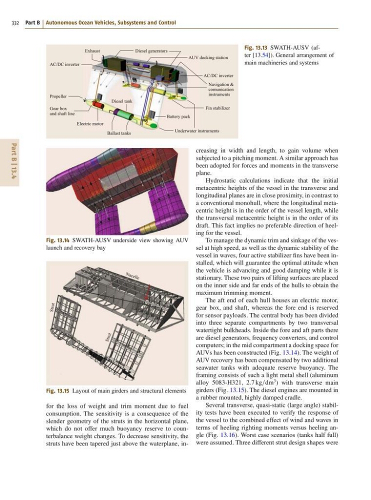
The aft end of each hull houses an electric motor,
gear box, and shaft, whereas the fore end is reserved
for sensor payloads. The central body has been divided
into three separate compartments by two transversal
watertight bulkheads. Inside the fore and aft parts there
are diesel generators, frequency converters, and control
computers; in the mid compartment a docking space for
AUVs has been constructed (Fig. 13.14). The weight of
AUV recovery has been compensated by two additional
seawater tanks with adequate reserve buoyancy. The
framing consists of such a light metal shell (aluminum
alloy 5083-H321, 2:7 kg=dm
3 ) with transverse main
girders (Fig. 13.15). The diesel engines are mounted in
a rubber mounted, highly damped cradle.
Several transverse, quasi-static (large angle) stability tests have been executed to verify the response of
the vessel to the combined effect of wind and waves in
terms of heeling righting moments versus heeling angle (Fig. 13.16). Worst case scenarios (tanks half full)
were assumed. Three different strut design shapes were
332 Part B Autonomous Ocean Vehicles, Subsystems and Control
AC/DC inverter
AC/DC inverter
Diesel generators
AUV docking station
Propeller
Gear box
and shaft line
Navigation &
comunication
instruments
Fin stabilizer
Battery pack
Underwater instruments
Electric motor
Ballast tanks
Diesel tank
Exhaust
Fig. 13.13 SWATH-AUSV (after [13.54]). General arrangement of
main machineries and systems
Fig. 13.14 SWATH-AUSV underside view showing AUV
launch and recovery bay
St ru t
S tr u t
N ac el le
Fig. 13.15 Layout of main girders and structural elements
for the loss of weight and trim moment due to fuel
consumption. The sensitivity is a consequence of the
slender geometry of the struts in the horizontal plane,
which do not offer much buoyancy reserve to counterbalance weight changes. To decrease sensitivity, the
struts have been tapered just above the waterplane, increasing in width and length, to gain volume when
subjected to a pitching moment. A similar approach has
been adopted for forces and moments in the transverse
plane.
Hydrostatic calculations indicate that the initial
metacentric heights of the vessel in the transverse and
longitudinal planes are in close proximity, in contrast to
a conventional monohull, where the longitudinal metacentric height is in the order of the vessel length, while
the transversal metacentric height is in the order of its
draft. This fact implies no preferable direction of heeling for the vessel.
To manage the dynamic trim and sinkage of the vessel at high speed, as well as the dynamic stability of the
vessel in waves, four active stabilizer fins have been installed, which will guarantee the optimal attitude when
the vehicle is advancing and good damping while it is
stationary. These two pairs of lifting surfaces are placed
on the inner side and far ends of the hulls to obtain the
maximum trimming moment.
The aft end of each hull houses an electric motor,
gear box, and shaft, whereas the fore end is reserved
for sensor payloads. The central body has been divided
into three separate compartments by two transversal
watertight bulkheads. Inside the fore and aft parts there
are diesel generators, frequency converters, and control
computers; in the mid compartment a docking space for
AUVs has been constructed (Fig. 13.14). The weight of
AUV recovery has been compensated by two additional
seawater tanks with adequate reserve buoyancy. The
framing consists of such a light metal shell (aluminum
alloy 5083-H321, 2:7 kg=dm
3 ) with transverse main
girders (Fig. 13.15). The diesel engines are mounted in
a rubber mounted, highly damped cradle.
Several transverse, quasi-static (large angle) stability tests have been executed to verify the response of
the vessel to the combined effect of wind and waves in
terms of heeling righting moments versus heeling angle (Fig. 13.16). Worst case scenarios (tanks half full)
were assumed. Three different strut design shapes were