

Part B | 12.4
316 Part B Autonomous Ocean Vehicles, Subsystems and Control
Single payload winged-body of revolution
Single payload flying wing
Variable payload winged-body of revolution
Thermal glider
0
2
4
6
8
Loaded mass M = B/g (kg)
Maximum cross (horizontal) speed u max (m/s)
10000
1000
100
10
1
0.1
0.01
Fig. 12.14 Maximum cross-country (horizontal) speed for an underwater glider due to variation in the loaded mass for a winged body
of revolution carrying single (small) payloads (red), a winged body
of revolution carrying variable (large) payloads (blue), the flying
wing carrying single (small) payloads (green), and a thermal glider
in a winged-body-of-revolution configuration with single payload
(purple)
wing carrying single (small) payloads (green), and the
thermal glider in a winged-body-of-revolution configuration with single payload (purple). Winged bodies
of revolution with maximum buoyancy engine capacity are the optimal combination for maximum speed
(Fig. 12.15). For a given n b , flying wings of equivalent
vehicle volume are slower than winged bodies of revolution, but have superior transport economy, requiring
fewer dive cycles (and less near surface exposure time)
for a given distance traveled.
To exploit the superior horizontal transport economy
of the flying wing for large payloads and cargo, vehicle packing must deal with the planar form factor of the
flying wing and distribute the vehicle weight such that
the critical vehicle balance factors that provide stability are met both before and after payload/cargo delivery.
Those critical balance factors are (1) adequate vertical
separation between the centers of buoyancy and mass,
and (2) adequate horizontal separation between the centers of pressure and mass. A large payload/cargo concept
for the flying wing glider is based on the use of multiple
wing systems, and is referred to as the Coanda triplane,
Fig. 12.16. The concept is based on adding two auxiliary wings to the basic ZRay flying wing glider hull
form. To assure maximum vertical separation between
the centers of buoyancy and mass, the lower wing carries the negatively buoyant payload/cargo while the upper wing carries buoyancy-compensating foam. This arrangement allows the glider to deliver the payload/cargo
a)
b)
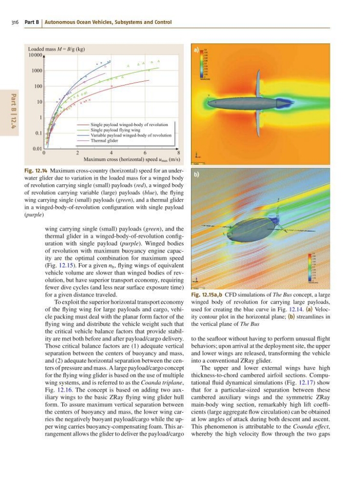
Fig. 12.15a,b CFD simulations of The Bus concept, a large
winged body of revolution for carrying large payloads,
used for creating the blue curve in Fig. 12.14. (a) Velocity contour plot in the horizontal plane; (b) streamlines in
the vertical plane of The Bus
to the seafloor without having to perform unusual flight
behaviors; upon arrival at the deployment site, the upper
and lower wings are released, transforming the vehicle
into a conventional ZRay glider.
The upper and lower external wings have high
thickness-to-chord cambered airfoil sections. Computational fluid dynamical simulations (Fig. 12.17) show
that for a particular-sized separation between these
cambered auxiliary wings and the symmetric ZRay
main-body wing section, remarkably high lift coefficients (large aggregate flow circulation) can be obtained
at low angles of attack during both descent and ascent.
This phenomenon is attributable to the Coanda effect,
whereby the high velocity flow through the two gaps
316 Part B Autonomous Ocean Vehicles, Subsystems and Control
Single payload winged-body of revolution
Single payload flying wing
Variable payload winged-body of revolution
Thermal glider
0
2
4
6
8
Loaded mass M = B/g (kg)
Maximum cross (horizontal) speed u max (m/s)
10000
1000
100
10
1
0.1
0.01
Fig. 12.14 Maximum cross-country (horizontal) speed for an underwater glider due to variation in the loaded mass for a winged body
of revolution carrying single (small) payloads (red), a winged body
of revolution carrying variable (large) payloads (blue), the flying
wing carrying single (small) payloads (green), and a thermal glider
in a winged-body-of-revolution configuration with single payload
(purple)
wing carrying single (small) payloads (green), and the
thermal glider in a winged-body-of-revolution configuration with single payload (purple). Winged bodies
of revolution with maximum buoyancy engine capacity are the optimal combination for maximum speed
(Fig. 12.15). For a given n b , flying wings of equivalent
vehicle volume are slower than winged bodies of revolution, but have superior transport economy, requiring
fewer dive cycles (and less near surface exposure time)
for a given distance traveled.
To exploit the superior horizontal transport economy
of the flying wing for large payloads and cargo, vehicle packing must deal with the planar form factor of the
flying wing and distribute the vehicle weight such that
the critical vehicle balance factors that provide stability are met both before and after payload/cargo delivery.
Those critical balance factors are (1) adequate vertical
separation between the centers of buoyancy and mass,
and (2) adequate horizontal separation between the centers of pressure and mass. A large payload/cargo concept
for the flying wing glider is based on the use of multiple
wing systems, and is referred to as the Coanda triplane,
Fig. 12.16. The concept is based on adding two auxiliary wings to the basic ZRay flying wing glider hull
form. To assure maximum vertical separation between
the centers of buoyancy and mass, the lower wing carries the negatively buoyant payload/cargo while the upper wing carries buoyancy-compensating foam. This arrangement allows the glider to deliver the payload/cargo
a)
b)
Fig. 12.15a,b CFD simulations of The Bus concept, a large
winged body of revolution for carrying large payloads,
used for creating the blue curve in Fig. 12.14. (a) Velocity contour plot in the horizontal plane; (b) streamlines in
the vertical plane of The Bus
to the seafloor without having to perform unusual flight
behaviors; upon arrival at the deployment site, the upper
and lower wings are released, transforming the vehicle
into a conventional ZRay glider.
The upper and lower external wings have high
thickness-to-chord cambered airfoil sections. Computational fluid dynamical simulations (Fig. 12.17) show
that for a particular-sized separation between these
cambered auxiliary wings and the symmetric ZRay
main-body wing section, remarkably high lift coefficients (large aggregate flow circulation) can be obtained
at low angles of attack during both descent and ascent.
This phenomenon is attributable to the Coanda effect,
whereby the high velocity flow through the two gaps