

Control Theory and Applications 10.5 Course-Keeping Autopilots 271
Part A | 10.5
10.5.3 PID Autopilots
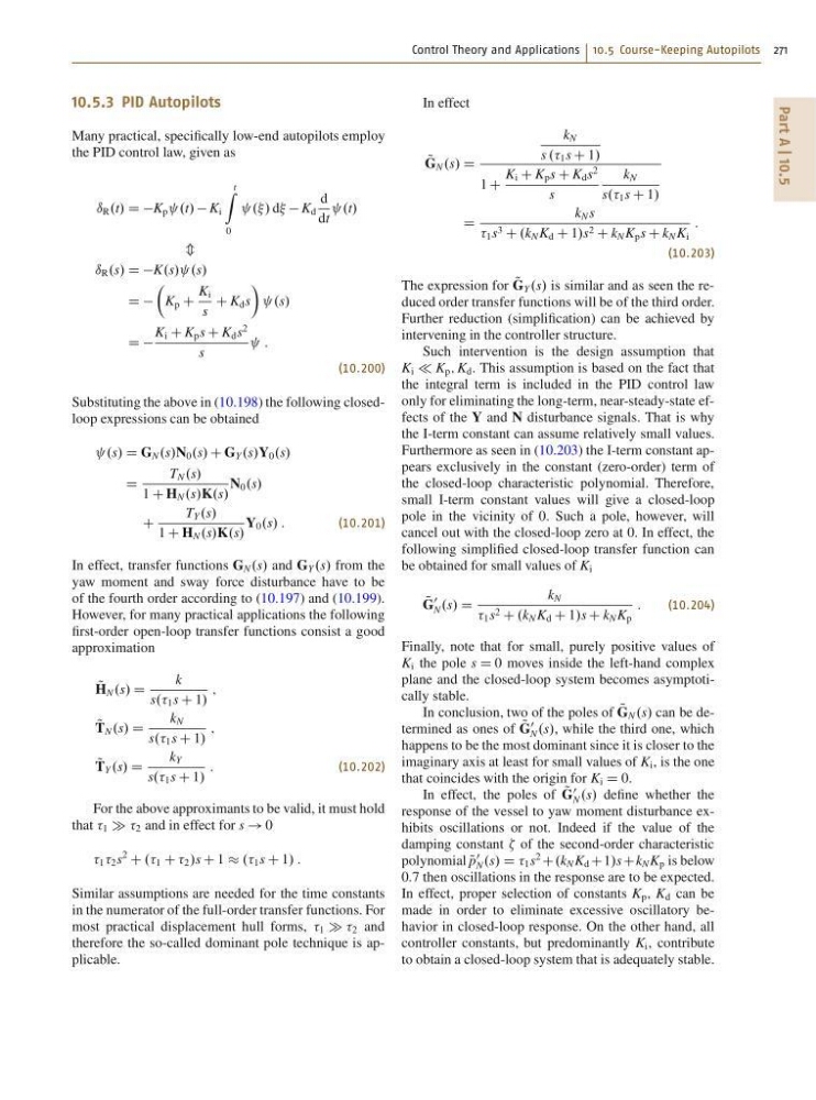
Many practical, specifically low-end autopilots employ
the PID control law, given as
ı R .t/ D DK p .t/ K i
t
Z
0
../ d K d
d
dt
.t/
m
ı R .s/ D DK.s/ .s/
D D
Â
K p C
K i
s
C K d s
Ã
.s/
D D
K i C K p s C K d s
2
s
:
(10.200)
Substituting the above in (10.198) the following closedloop expressions can be obtained
.s/ D G N .s/N 0 .s/ C G Y .s/Y 0 .s/
D
T N .s/
1 C H N .s/K.s/
N 0 .s/
C
T Y .s/
1 C H N .s/K.s/
Y 0 .s/ :
(10.201)
In effect, transfer functions G N .s/ and G Y .s/ from the
yaw moment and sway force disturbance have to be
of the fourth order according to (10.197) and (10.199).
However, for many practical applications the following
first-order open-loop transfer functions consist a good
approximation
Q
H N .s/ D
k
s.. 1 s C 1/
;
Q
T N .s/ D
k N
s.. 1 s C 1/
;
Q
T Y .s/ D
k Y
s.. 1 s C 1/
:
(10.202)
For the above approximants to be valid, it must hold
that 1 2 and in effect for s ! 0
1 2 s
2
C .. 1 C 2 /s C 1 .. 1 s C 1/ :
Similar assumptions are needed for the time constants
in the numerator of the full-order transfer functions. For
most practical displacement hull forms, 1 2 and
therefore the so-called dominant pole technique is applicable.
In effect
Q
G N .s/ D
k N
s .. 1 s C 1/
1 C
K i C K p s C K d s
2
s
k N
s.. 1 s C 1/
D
k N s
1 s 3 C .k N K d C 1/s 2 C k N K p s C k N K i
:
(10.203)
The expression for Q
G Y .s/ is similar and as seen the reduced order transfer functions will be of the third order.
Further reduction (simplification) can be achieved by
intervening in the controller structure.
Such intervention is the design assumption that
K i K p ; K d . This assumption is based on the fact that
the integral term is included in the PID control law
only for eliminating the long-term, near-steady-state effects of the Y and N disturbance signals. That is why
the I-term constant can assume relatively small values.
Furthermore as seen in (10.203) the I-term constant appears exclusively in the constant (zero-order) term of
the closed-loop characteristic polynomial. Therefore,
small I-term constant values will give a closed-loop
pole in the vicinity of 0. Such a pole, however, will
cancel out with the closed-loop zero at 0. In effect, the
following simplified closed-loop transfer function can
be obtained for small values of K i
Q
G
0
N .s/ D
k N
1 s 2 C .k N K d C 1/s C k N K p
:
(10.204)
Finally, note that for small, purely positive values of
K i the pole s D 0 moves inside the left-hand complex
plane and the closed-loop system becomes asymptotically stable.
In conclusion, two of the poles of Q
G N .s/ can be determined as ones of Q
G
0
N .s/, while the third one, which
happens to be the most dominant since it is closer to the
imaginary axis at least for small values of K i , is the one
that coincides with the origin for K i D 0.
In effect, the poles of Q
G
0
N .s/ define whether the
response of the vessel to yaw moment disturbance exhibits oscillations or not. Indeed if the value of the
damping constant of the second-order characteristic
polynomial Q
p
0
N .s/ D 1 s
2
C.k N K d C1/sCk N K p is below
0.7 then oscillations in the response are to be expected.
In effect, proper selection of constants K p , K d can be
made in order to eliminate excessive oscillatory behavior in closed-loop response. On the other hand, all
controller constants, but predominantly K i , contribute
to obtain a closed-loop system that is adequately stable.
Part A | 10.5
10.5.3 PID Autopilots
Many practical, specifically low-end autopilots employ
the PID control law, given as
ı R .t/ D DK p .t/ K i
t
Z
0
../ d K d
d
dt
.t/
m
ı R .s/ D DK.s/ .s/
D D
Â
K p C
K i
s
C K d s
Ã
.s/
D D
K i C K p s C K d s
2
s
:
(10.200)
Substituting the above in (10.198) the following closedloop expressions can be obtained
.s/ D G N .s/N 0 .s/ C G Y .s/Y 0 .s/
D
T N .s/
1 C H N .s/K.s/
N 0 .s/
C
T Y .s/
1 C H N .s/K.s/
Y 0 .s/ :
(10.201)
In effect, transfer functions G N .s/ and G Y .s/ from the
yaw moment and sway force disturbance have to be
of the fourth order according to (10.197) and (10.199).
However, for many practical applications the following
first-order open-loop transfer functions consist a good
approximation
Q
H N .s/ D
k
s.. 1 s C 1/
;
Q
T N .s/ D
k N
s.. 1 s C 1/
;
Q
T Y .s/ D
k Y
s.. 1 s C 1/
:
(10.202)
For the above approximants to be valid, it must hold
that 1 2 and in effect for s ! 0
1 2 s
2
C .. 1 C 2 /s C 1 .. 1 s C 1/ :
Similar assumptions are needed for the time constants
in the numerator of the full-order transfer functions. For
most practical displacement hull forms, 1 2 and
therefore the so-called dominant pole technique is applicable.
In effect
Q
G N .s/ D
k N
s .. 1 s C 1/
1 C
K i C K p s C K d s
2
s
k N
s.. 1 s C 1/
D
k N s
1 s 3 C .k N K d C 1/s 2 C k N K p s C k N K i
:
(10.203)
The expression for Q
G Y .s/ is similar and as seen the reduced order transfer functions will be of the third order.
Further reduction (simplification) can be achieved by
intervening in the controller structure.
Such intervention is the design assumption that
K i K p ; K d . This assumption is based on the fact that
the integral term is included in the PID control law
only for eliminating the long-term, near-steady-state effects of the Y and N disturbance signals. That is why
the I-term constant can assume relatively small values.
Furthermore as seen in (10.203) the I-term constant appears exclusively in the constant (zero-order) term of
the closed-loop characteristic polynomial. Therefore,
small I-term constant values will give a closed-loop
pole in the vicinity of 0. Such a pole, however, will
cancel out with the closed-loop zero at 0. In effect, the
following simplified closed-loop transfer function can
be obtained for small values of K i
Q
G
0
N .s/ D
k N
1 s 2 C .k N K d C 1/s C k N K p
:
(10.204)
Finally, note that for small, purely positive values of
K i the pole s D 0 moves inside the left-hand complex
plane and the closed-loop system becomes asymptotically stable.
In conclusion, two of the poles of Q
G N .s/ can be determined as ones of Q
G
0
N .s/, while the third one, which
happens to be the most dominant since it is closer to the
imaginary axis at least for small values of K i , is the one
that coincides with the origin for K i D 0.
In effect, the poles of Q
G
0
N .s/ define whether the
response of the vessel to yaw moment disturbance exhibits oscillations or not. Indeed if the value of the
damping constant of the second-order characteristic
polynomial Q
p
0
N .s/ D 1 s
2
C.k N K d C1/sCk N K p is below
0.7 then oscillations in the response are to be expected.
In effect, proper selection of constants K p , K d can be
made in order to eliminate excessive oscillatory behavior in closed-loop response. On the other hand, all
controller constants, but predominantly K i , contribute
to obtain a closed-loop system that is adequately stable.