

Part A | 10.5
270 Part A Fundamentals
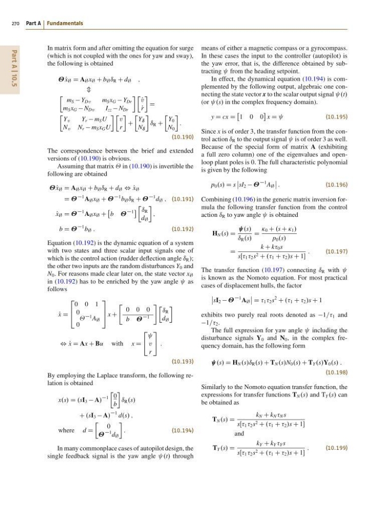
In matrix form and after omitting the equation for surge
(which is not coupled with the ones for yaw and sway),
the following is obtained
P
x ; D A ; x ; C b ; ı R C d ; ;
m
Ä
m S Y Dv
m S x G Y Dr
m S x G N Dv
I zz N Dr
Ä P
v
P
r
D
Ä
Y v
Y r m S U
N v N r m S x G U
Ä
v
r
C
Ä
Y ı
N ı
ı R C
Ä
Y 0
N 0
:
(10.190)
The correspondence between the brief and extended
versions of (10.190) is obvious.
Assuming that matrix in (10.190) is invertible the
following are obtained
P
x ; D A ; x ; C b ; ı R C d ; , P
x ;
D
1 A ; x ; C
1 b ; ı R C
1 d ; ; (10.191)
P
x ; D
1 A ; x ; C
b
1
Ä ı R
d ;
;
b D
1 b ; :
(10.192)
Equation (10.192) is the dynamic equation of a system
with two states and three scalar input signals one of
which is the control action (rudder deflection angle ı R );
the other two inputs are the random disturbances Y 0 and
N 0 . For reasons made clear later on, the state vector x ;
in (10.192) has to be enriched by the yaw angle as
follows
P
x D
2
6
4
0 0 1
0
0
1 A ;
3
7
5 x C
"
0 0 0
b
1
# Ä ı R
d ;
, P
x D Ax C Bu with x D
2
4 v
r
3
5 :
(10.193)
By employing the Laplace transform, the following relation is obtained
x.s/ D .sI 3 A/
1
Ä
0
b
ı R .s/
C .sI 3 A/
1 d.s/ ;
where d D
Ä
0
1 d ;
:
(10.194)
In many commonplace cases of autopilot design, the
single feedback signal is the yaw angle .t/ through
means of either a magnetic compass or a gyrocompass.
In these cases the input to the controller (autopilot) is
the yaw error, that is, the difference obtained by subtracting from the heading setpoint.
In effect, the dynamical equation (10.194) is complemented by the following output, algebraic one connecting the state vector x to the scalar output signal .t/
(or .s/ in the complex frequency domain).
y D cx D
1 0 0
x D
(10.195)
Since x is of order 3, the transfer function from the control action ı R to the output signal is of order 3 as well.
Because of the special form of matrix A (exhibiting
a full zero column) one of the eigenvalues and openloop plant poles is 0. The full characteristic polynomial
is given by the following
p 0 .s/ D s
ˇ
ˇ sI 2
1 A ;
ˇ
ˇ :
(10.196)
Combining (10.196) in the generic matrix inversion formula the following transfer function from the control
action ı R to yaw angle is obtained
H N .s/ D
.s/
ı R .s/
D
Ä 0 C .s C Ä 1 /
p 0 .s/
D
k C k 0 s
sŒŒ 1 2 s 2 C .. 1 C 2 /s C 1
:
(10.197)
The transfer function (10.197) connecting ı R with
is known as the Nomoto equation. For most practical
cases of displacement hulls, the factor
ˇ
ˇ sI 2
1 A ;
ˇ
ˇ D 1 2 s
2
C .. 1 C 2 /s C 1
exhibits two purely real roots denoted as 1== 1 and
1== 2 .
The full expression for yaw angle including the
disturbance signals Y 0 and N 0 , in the complex frequency domain, has the following form
.s/ D H N .s/ı R .s/ C T N .s/N 0 .s/ C T Y .s/Y 0 .s/ :
(10.198)
Similarly to the Nomoto equation transfer function, the
expressions for transfer functions T N .s/ and T Y .s/ can
be obtained as
T N .s/ D
k N C k N N s
sŒŒ 1 2 s 2 C .. 1 C 2 /s C 1
and
T Y .s/ D
k Y C k Y Y s
sŒŒ 1 2 s 2 C .. 1 C 2 /s C 1
:
(10.199)
270 Part A Fundamentals
In matrix form and after omitting the equation for surge
(which is not coupled with the ones for yaw and sway),
the following is obtained
P
x ; D A ; x ; C b ; ı R C d ; ;
m
Ä
m S Y Dv
m S x G Y Dr
m S x G N Dv
I zz N Dr
Ä P
v
P
r
D
Ä
Y v
Y r m S U
N v N r m S x G U
Ä
v
r
C
Ä
Y ı
N ı
ı R C
Ä
Y 0
N 0
:
(10.190)
The correspondence between the brief and extended
versions of (10.190) is obvious.
Assuming that matrix in (10.190) is invertible the
following are obtained
P
x ; D A ; x ; C b ; ı R C d ; , P
x ;
D
1 A ; x ; C
1 b ; ı R C
1 d ; ; (10.191)
P
x ; D
1 A ; x ; C
b
1
Ä ı R
d ;
;
b D
1 b ; :
(10.192)
Equation (10.192) is the dynamic equation of a system
with two states and three scalar input signals one of
which is the control action (rudder deflection angle ı R );
the other two inputs are the random disturbances Y 0 and
N 0 . For reasons made clear later on, the state vector x ;
in (10.192) has to be enriched by the yaw angle as
follows
P
x D
2
6
4
0 0 1
0
0
1 A ;
3
7
5 x C
"
0 0 0
b
1
# Ä ı R
d ;
, P
x D Ax C Bu with x D
2
4 v
r
3
5 :
(10.193)
By employing the Laplace transform, the following relation is obtained
x.s/ D .sI 3 A/
1
Ä
0
b
ı R .s/
C .sI 3 A/
1 d.s/ ;
where d D
Ä
0
1 d ;
:
(10.194)
In many commonplace cases of autopilot design, the
single feedback signal is the yaw angle .t/ through
means of either a magnetic compass or a gyrocompass.
In these cases the input to the controller (autopilot) is
the yaw error, that is, the difference obtained by subtracting from the heading setpoint.
In effect, the dynamical equation (10.194) is complemented by the following output, algebraic one connecting the state vector x to the scalar output signal .t/
(or .s/ in the complex frequency domain).
y D cx D
1 0 0
x D
(10.195)
Since x is of order 3, the transfer function from the control action ı R to the output signal is of order 3 as well.
Because of the special form of matrix A (exhibiting
a full zero column) one of the eigenvalues and openloop plant poles is 0. The full characteristic polynomial
is given by the following
p 0 .s/ D s
ˇ
ˇ sI 2
1 A ;
ˇ
ˇ :
(10.196)
Combining (10.196) in the generic matrix inversion formula the following transfer function from the control
action ı R to yaw angle is obtained
H N .s/ D
.s/
ı R .s/
D
Ä 0 C .s C Ä 1 /
p 0 .s/
D
k C k 0 s
sŒŒ 1 2 s 2 C .. 1 C 2 /s C 1
:
(10.197)
The transfer function (10.197) connecting ı R with
is known as the Nomoto equation. For most practical
cases of displacement hulls, the factor
ˇ
ˇ sI 2
1 A ;
ˇ
ˇ D 1 2 s
2
C .. 1 C 2 /s C 1
exhibits two purely real roots denoted as 1== 1 and
1== 2 .
The full expression for yaw angle including the
disturbance signals Y 0 and N 0 , in the complex frequency domain, has the following form
.s/ D H N .s/ı R .s/ C T N .s/N 0 .s/ C T Y .s/Y 0 .s/ :
(10.198)
Similarly to the Nomoto equation transfer function, the
expressions for transfer functions T N .s/ and T Y .s/ can
be obtained as
T N .s/ D
k N C k N N s
sŒŒ 1 2 s 2 C .. 1 C 2 /s C 1
and
T Y .s/ D
k Y C k Y Y s
sŒŒ 1 2 s 2 C .. 1 C 2 /s C 1
:
(10.199)