

Part A | 10.5
268 Part A Fundamentals
Heave
Surge
Sway
Roll
Pitch
Yaw
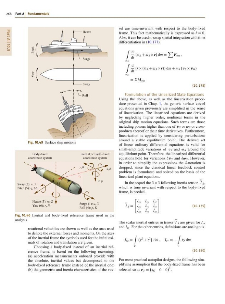
Fig. 10.45 Surface ship motions
y, θ
x, φ
z, ψ
r o
Heave (3): w, Z
Yaw (6): r, N
Sway (2): v, Y
Pitch (5): q, M
Surge (1): u, X
Roll (4): p, K
Body-fixed
coordinate system
Inertial or Earth-fixed
coordinate system
Fig. 10.46 Inertial and body-fixed reference frame used in the
analysis
rotational velocities are shown as well as the ones used
to denote the external forces and moments. On the axes
of the inertial frame the symbols used for the infinitesimals of rotation and translation are given.
Choosing a body-fixed instead of an inertial reference frame, is based on the following reasoning:
(a) acceleration measurements onboard provide with
the absolute, inertial values but decomposed to the
body-fixed reference frame instead of the inertial one;
(b) the geometric and inertia characteristics of the vessel are time-invariant with respect to the body-fixed
frame. This fact mathematically is expressed as P
r D 0.
Also, it can be used to swap spatial integration with time
differentiation in (10.177).
Z
mS
d
dt
fv S C ! S rg dm D
X
F ext ;
Z
mS
d
dt
fr .v S C ! S r/g dm C m S .v S v G /
D ˙M ext
(10.178)
Formulation of the Linearized State Equations
Using the above, as well as the linearization procedure presented in Chap. 1, the generic surface vessel
equations given previously are simplified in the sense
of linearization. The linearized equations are derived
by neglecting higher order, nonlinear terms in the
original ship motion equations. Such terms are those
including powers higher than one of v S or ! S or crossproducts thereof or their time derivatives. Furthermore,
linearization is applied by considering perturbations
around a stable equilibrium point. The derived set
of linear ordinary differential equations is valid for
small-amplitude variations of v S and ! S around the
equilibrium point. Therefore, the linearized differential
equations hold for variations ıv S and ı! S . However,
in order to simplify the expressions the ı-notation is
dropped, since the classical linear feedback control
problem is formulated and solved on the basis of the
linearized plant equations.
In the sequel the 3 3 following inertia tensor,
$
I S ,
which is time invariant with respect to the body-fixed
frame, is needed.
$
I S D
2
4
I xx I xy I xz
I xy I yy I yz
I xz I yz I zz
3
5
(10.179)
The scalar inertial entries in tensor
$
I S are given for I xx
and I xy . For the other entries, definitions are analogous.
I xx D
Z
V
y
2
C z
2
dm ; I xy D D
Z
V
xy dm
(10.180)
For most practical autopilot designs, the following simplifying assumption that the body-fixed frame has been
selected so as r G D
x G 0 0
T .
268 Part A Fundamentals
Heave
Surge
Sway
Roll
Pitch
Yaw
Fig. 10.45 Surface ship motions
y, θ
x, φ
z, ψ
r o
Heave (3): w, Z
Yaw (6): r, N
Sway (2): v, Y
Pitch (5): q, M
Surge (1): u, X
Roll (4): p, K
Body-fixed
coordinate system
Inertial or Earth-fixed
coordinate system
Fig. 10.46 Inertial and body-fixed reference frame used in the
analysis
rotational velocities are shown as well as the ones used
to denote the external forces and moments. On the axes
of the inertial frame the symbols used for the infinitesimals of rotation and translation are given.
Choosing a body-fixed instead of an inertial reference frame, is based on the following reasoning:
(a) acceleration measurements onboard provide with
the absolute, inertial values but decomposed to the
body-fixed reference frame instead of the inertial one;
(b) the geometric and inertia characteristics of the vessel are time-invariant with respect to the body-fixed
frame. This fact mathematically is expressed as P
r D 0.
Also, it can be used to swap spatial integration with time
differentiation in (10.177).
Z
mS
d
dt
fv S C ! S rg dm D
X
F ext ;
Z
mS
d
dt
fr .v S C ! S r/g dm C m S .v S v G /
D ˙M ext
(10.178)
Formulation of the Linearized State Equations
Using the above, as well as the linearization procedure presented in Chap. 1, the generic surface vessel
equations given previously are simplified in the sense
of linearization. The linearized equations are derived
by neglecting higher order, nonlinear terms in the
original ship motion equations. Such terms are those
including powers higher than one of v S or ! S or crossproducts thereof or their time derivatives. Furthermore,
linearization is applied by considering perturbations
around a stable equilibrium point. The derived set
of linear ordinary differential equations is valid for
small-amplitude variations of v S and ! S around the
equilibrium point. Therefore, the linearized differential
equations hold for variations ıv S and ı! S . However,
in order to simplify the expressions the ı-notation is
dropped, since the classical linear feedback control
problem is formulated and solved on the basis of the
linearized plant equations.
In the sequel the 3 3 following inertia tensor,
$
I S ,
which is time invariant with respect to the body-fixed
frame, is needed.
$
I S D
2
4
I xx I xy I xz
I xy I yy I yz
I xz I yz I zz
3
5
(10.179)
The scalar inertial entries in tensor
$
I S are given for I xx
and I xy . For the other entries, definitions are analogous.
I xx D
Z
V
y
2
C z
2
dm ; I xy D D
Z
V
xy dm
(10.180)
For most practical autopilot designs, the following simplifying assumption that the body-fixed frame has been
selected so as r G D
x G 0 0
T .