

Control Theory and Applications 10.3 SISO System Controls 249
Part A | 10.3
The control law, that is, the relationship connecting the error to the control signal as implemented in the
controller, is
u D
(
Asgn.e/ ; jej Z d
0 ;
jej < Z d
D
8
ˆ <
ˆ :
CA ; e CZ d
0 ;
jej < Z d
A ; e Ä ÄZ d :
(10.103)
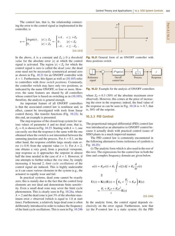
In the above, A is a constant and Z d 0 a threshold
value for the absolute error jej at which the control
signal is activated. The region jej < Z d for which the
control signal is zero is called the dead zone; the dead
zone need not be necessarily symmetrical around zero
as shown in Fig. 10.21 for an ON/OFF controller with
A D 1. Furthermore, this figure as well as (10.103) refer
to controllers with three switch positions. Commonly,
the controller switch may have only two positions, as
indicated by the name ON/OFF, or four or more. However, the same features are shared by all controllers
whose control law is based on switching as in (10.103);
therefore, the analysis is general enough.
An important feature of all ON/OFF controllers
is that the associated control law is nonlinear and, in
effect, cannot be investigated with tools from linear
control theory, like transfer functions (Fig. 10.22). In
this end, an example is presented.
The step response of the closed-loop system for various values of parameter A and no dead zone, that is,
Z d D 0, is shown in Fig. 10.23. Starting with A D 1, one
can easily see that the response is the same with the one
obtained when the switch is not intermitted between the
summing junction and the process. For A D 0:1, on the
other hand, the response exhibits large steady-state error ( 0:9) from the setpoint value (D 1). For A D 2,
one obtains a very good, from a practical viewpoint,
step response as it approaches the setpoint in almost
half the time needed in the case of A D 1. However, if
one attempts to further reduce the rise time, by simply
increasing A beyond 2, limit cycle oscillations of the
control signal are induced. This is highly undesirable
as it can cause various elements in the system (e.g., the
actuator) to rapidly wear and fail.
In practical systems, dead zone cannot be exactly
zero; this is mainly due to the fact that the control loop
elements are not ideal and demonstrate finite sensitivity. Even a small dead zone may sever the limit cycle
phenomenon. This is clearly seen in Fig. 10.24a, where
A D 2 and the dead zone is just 3% of the absolute maximum error e observed (which is equal to 1.0 at start
time). Furthermore, a relatively large dead zone is often
deliberately introduced in order to reduce the frequency
of the limit cycle oscillations. This is seen in Fig. 10.24b
u
+1
–1
e
Fig. 10.21 General form of an ON/OFF controller with
three positions switch
Process
On/off
control law
Reference
signal
A*sgn (u)
Response
y
1
5 s + 1
Fig. 10.22 Example for the analysis of ON/OFF controllers
where Z d D 0:3 (30% of the absolute maximum error
observed). However, this comes at the price of increasing the error in the response; indeed, the final value of
the response as can be seen in Fig. 10.24 is 0:7, that
is, 30% off the setpoint.
10.3.3 PID Control
The proportional-integral-differential (PID) control law
was introduced as an alternative to ON/OFF control because it actually deals with practical control issues of
SISO plants in a much improved manner.
The PID control law is commonly encountered in
the following alternative forms (reference of symbols is
Fig. 10.25):
(i) The analytic form which is also used in the rest of
this text. The expressions for the control law in both the
time and complex frequency domain are given below.
u.t/ D K p e.t/ C K i
t
Z
0
e../ d C K d
d
dt
e.t/
m
U.s/ D K.s/E.s/ D
Â
K p C
K i
s
C K d s
Ã
E.s/
D
K i C K p s C K d s
2
s
E.s/
(10.104)
In the analytic form, the control signal depends exclusively on the error signal. Furthermore, note that
(a) the P-control law is a static system; (b) the PID
Part A | 10.3
The control law, that is, the relationship connecting the error to the control signal as implemented in the
controller, is
u D
(
Asgn.e/ ; jej Z d
0 ;
jej < Z d
D
8
ˆ <
ˆ :
CA ; e CZ d
0 ;
jej < Z d
A ; e Ä ÄZ d :
(10.103)
In the above, A is a constant and Z d 0 a threshold
value for the absolute error jej at which the control
signal is activated. The region jej < Z d for which the
control signal is zero is called the dead zone; the dead
zone need not be necessarily symmetrical around zero
as shown in Fig. 10.21 for an ON/OFF controller with
A D 1. Furthermore, this figure as well as (10.103) refer
to controllers with three switch positions. Commonly,
the controller switch may have only two positions, as
indicated by the name ON/OFF, or four or more. However, the same features are shared by all controllers
whose control law is based on switching as in (10.103);
therefore, the analysis is general enough.
An important feature of all ON/OFF controllers
is that the associated control law is nonlinear and, in
effect, cannot be investigated with tools from linear
control theory, like transfer functions (Fig. 10.22). In
this end, an example is presented.
The step response of the closed-loop system for various values of parameter A and no dead zone, that is,
Z d D 0, is shown in Fig. 10.23. Starting with A D 1, one
can easily see that the response is the same with the one
obtained when the switch is not intermitted between the
summing junction and the process. For A D 0:1, on the
other hand, the response exhibits large steady-state error ( 0:9) from the setpoint value (D 1). For A D 2,
one obtains a very good, from a practical viewpoint,
step response as it approaches the setpoint in almost
half the time needed in the case of A D 1. However, if
one attempts to further reduce the rise time, by simply
increasing A beyond 2, limit cycle oscillations of the
control signal are induced. This is highly undesirable
as it can cause various elements in the system (e.g., the
actuator) to rapidly wear and fail.
In practical systems, dead zone cannot be exactly
zero; this is mainly due to the fact that the control loop
elements are not ideal and demonstrate finite sensitivity. Even a small dead zone may sever the limit cycle
phenomenon. This is clearly seen in Fig. 10.24a, where
A D 2 and the dead zone is just 3% of the absolute maximum error e observed (which is equal to 1.0 at start
time). Furthermore, a relatively large dead zone is often
deliberately introduced in order to reduce the frequency
of the limit cycle oscillations. This is seen in Fig. 10.24b
u
+1
–1
e
Fig. 10.21 General form of an ON/OFF controller with
three positions switch
Process
On/off
control law
Reference
signal
A*sgn (u)
Response
y
1
5 s + 1
Fig. 10.22 Example for the analysis of ON/OFF controllers
where Z d D 0:3 (30% of the absolute maximum error
observed). However, this comes at the price of increasing the error in the response; indeed, the final value of
the response as can be seen in Fig. 10.24 is 0:7, that
is, 30% off the setpoint.
10.3.3 PID Control
The proportional-integral-differential (PID) control law
was introduced as an alternative to ON/OFF control because it actually deals with practical control issues of
SISO plants in a much improved manner.
The PID control law is commonly encountered in
the following alternative forms (reference of symbols is
Fig. 10.25):
(i) The analytic form which is also used in the rest of
this text. The expressions for the control law in both the
time and complex frequency domain are given below.
u.t/ D K p e.t/ C K i
t
Z
0
e../ d C K d
d
dt
e.t/
m
U.s/ D K.s/E.s/ D
Â
K p C
K i
s
C K d s
Ã
E.s/
D
K i C K p s C K d s
2
s
E.s/
(10.104)
In the analytic form, the control signal depends exclusively on the error signal. Furthermore, note that
(a) the P-control law is a static system; (b) the PID