

Control Theory and Applications 10.2 Analysis of LTI Systems 243
Part A | 10.2
Factor .i!/. For the magnitude Bode plot of a transfer
function that contains this factor as part of its denominator, the contribution consists of a straight line with
slope 20 dB=dec (decibels per decade). For the phase
Bode plot of a transfer function that contains this factor
as part of its denominator, the contribution consists of
a horizontal straight line as follows
A.!/ D D20 log ! and '.!/ D D90
ı
:
(10.85)
In the case that the pole has multiplicity q > 1, as for example in (10.79), then (10.85) is modified accordingly.
A.!/ D D20q log ! and
'.!/ D Dq90
ı
(10.86)
Finally, if factor .i!/ appears on the numerator instead
the denominator of the transfer function the above still
hold but the sign has to be switched to positive.
Factor .1 C i!T /. Calculation of the contribution of
this factor, when appearing as part of the denominator
of the transfer function, is done on the basis of the following approximations
A.!/ D D20 log j1 C i!Tj
D D20 log
p
1 C ! 2 T 2
8
ˆ <
ˆ :
0
!T 1
3
!T ' 1
20 log .!T/ !T 1
;
(10.87)
'.!/ D D arctan .!T/
(
0
ı
!T < 0:1
90
ı
!T > 10:0
:
(10.88)
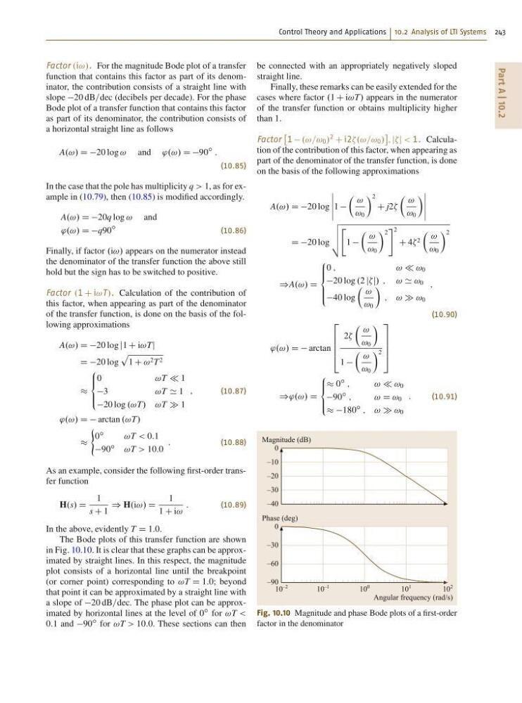
As an example, consider the following first-order transfer function
H.s/ D
1
s C 1
) H.i!/ D
1
1 C i!
:
(10.89)
In the above, evidently T D 1:0.
The Bode plots of this transfer function are shown
in Fig. 10.10. It is clear that these graphs can be approximated by straight lines. In this respect, the magnitude
plot consists of a horizontal line until the breakpoint
(or corner point) corresponding to !T D 1:0; beyond
that point it can be approximated by a straight line with
a slope of 20 dB=dec. The phase plot can be approximated by horizontal lines at the level of 0
ı for !T <
0:1 and 90
ı for !T > 10:0. These sections can then
be connected with an appropriately negatively sloped
straight line.
Finally, these remarks can be easily extended for the
cases where factor .1 C i!T/ appears in the numerator
of the transfer function or obtains multiplicity higher
than 1.
Factor
1 .!=! 0 /
2
C i2 0 /
; jj < 1. Calculation of the contribution of this factor, when appearing as
part of the denominator of the transfer function, is done
on the basis of the following approximations
A.!/ D D20 log
ˇ
ˇ
ˇ
ˇ
ˇ
1
 !
! 0
à 2
C j2
 !
! 0
à ˇ
ˇ
ˇ
ˇ
ˇ
D D20 log
v
u
u
t
"
1
 !
! 0
à 2
# 2
C 4 2
 !
! 0
à 2
)A.!/ D
8
ˆ ˆ <
ˆ ˆ :
0 ;
! ! 0
20 log .2 jj/ ; ! ' ! 0
40 log
 !
! 0
Ã
; ! ! 0
;
(10.90)
'.!/ D D arctan
2
6
6
6
4
2
 !
! 0
Ã
1
 !
! 0
à 2
3
7
7
7
5
)'.!/ D
8
ˆ <
ˆ :
0
ı
;
! ! 0
90
ı
;
!D ! 0
180
ı
; ! ! 0
:
(10.91)
Magnitude (dB)
0
–10
–20
–30
–40
10
–2
10
–1
10
0
10
2
10
1
Phase (deg)
Angular frequency (rad/s)
0
–30
–60
–90
Fig. 10.10 Magnitude and phase Bode plots of a first-order
factor in the denominator
Part A | 10.2
Factor .i!/. For the magnitude Bode plot of a transfer
function that contains this factor as part of its denominator, the contribution consists of a straight line with
slope 20 dB=dec (decibels per decade). For the phase
Bode plot of a transfer function that contains this factor
as part of its denominator, the contribution consists of
a horizontal straight line as follows
A.!/ D D20 log ! and '.!/ D D90
ı
:
(10.85)
In the case that the pole has multiplicity q > 1, as for example in (10.79), then (10.85) is modified accordingly.
A.!/ D D20q log ! and
'.!/ D Dq90
ı
(10.86)
Finally, if factor .i!/ appears on the numerator instead
the denominator of the transfer function the above still
hold but the sign has to be switched to positive.
Factor .1 C i!T /. Calculation of the contribution of
this factor, when appearing as part of the denominator
of the transfer function, is done on the basis of the following approximations
A.!/ D D20 log j1 C i!Tj
D D20 log
p
1 C ! 2 T 2
8
ˆ <
ˆ :
0
!T 1
3
!T ' 1
20 log .!T/ !T 1
;
(10.87)
'.!/ D D arctan .!T/
(
0
ı
!T < 0:1
90
ı
!T > 10:0
:
(10.88)
As an example, consider the following first-order transfer function
H.s/ D
1
s C 1
) H.i!/ D
1
1 C i!
:
(10.89)
In the above, evidently T D 1:0.
The Bode plots of this transfer function are shown
in Fig. 10.10. It is clear that these graphs can be approximated by straight lines. In this respect, the magnitude
plot consists of a horizontal line until the breakpoint
(or corner point) corresponding to !T D 1:0; beyond
that point it can be approximated by a straight line with
a slope of 20 dB=dec. The phase plot can be approximated by horizontal lines at the level of 0
ı for !T <
0:1 and 90
ı for !T > 10:0. These sections can then
be connected with an appropriately negatively sloped
straight line.
Finally, these remarks can be easily extended for the
cases where factor .1 C i!T/ appears in the numerator
of the transfer function or obtains multiplicity higher
than 1.
Factor
1 .!=! 0 /
2
C i2 0 /
; jj < 1. Calculation of the contribution of this factor, when appearing as
part of the denominator of the transfer function, is done
on the basis of the following approximations
A.!/ D D20 log
ˇ
ˇ
ˇ
ˇ
ˇ
1
 !
! 0
à 2
C j2
 !
! 0
à ˇ
ˇ
ˇ
ˇ
ˇ
D D20 log
v
u
u
t
"
1
 !
! 0
à 2
# 2
C 4 2
 !
! 0
à 2
)A.!/ D
8
ˆ ˆ <
ˆ ˆ :
0 ;
! ! 0
20 log .2 jj/ ; ! ' ! 0
40 log
 !
! 0
Ã
; ! ! 0
;
(10.90)
'.!/ D D arctan
2
6
6
6
4
2
 !
! 0
Ã
1
 !
! 0
à 2
3
7
7
7
5
)'.!/ D
8
ˆ <
ˆ :
0
ı
;
! ! 0
90
ı
;
!D ! 0
180
ı
; ! ! 0
:
(10.91)
Magnitude (dB)
0
–10
–20
–30
–40
10
–2
10
–1
10
0
10
2
10
1
Phase (deg)
Angular frequency (rad/s)
0
–30
–60
–90
Fig. 10.10 Magnitude and phase Bode plots of a first-order
factor in the denominator