

Ocean Electromagnetics 8.5 Plane Wave Incident on Seawater 185
Part A | 8.5
Using (8.75) and the identity cos  t D
p
1 sin
2
 t , the
term cos  t becomes
cos  t D
s
1
 iˇ a
˛ C iˇ
à 2
sin
2
 i ;
(8.76)
which can be reduced to a general form of
cos  t D se
i
:
(8.77)
It is clear that the wave transmitted into the sea will be
at an angle that is complex. The idea of a real and imaginary transmission angle needs further explanation.
The electric field for a perpendicular or parallel polarized field transmitted into seawater, (8.52) or (8.65),
can be written in a general form given by
E
t
D E
t
0 e
.x sin ÂtCz cos Ât/
;
(8.78)
that can be expanded to
E
t
D E
t
0 expŒ.˛ C iˇ/.x sin  t C z cos  t / : (8.79)
All the terms in front of the exponential in either (8.52)
or (8.65) have been lumped into E
t
0 . Placing (8.75) and
(8.77) into (8.79) gives
E
t
D E
t
0 exp
Ä
.˛ C iˇ/
Â
x
iˇ a
˛ C iˇ
sin  i
C zs.cos C i sin /
ÃÃ
;
(8.80)
and can be reduced to
E
t
D E
t
0 e
zp expŒi.xˇ a sin  i C zq/ ;
(8.81)
where
p D s.˛ cos ˇ sin / ;
(8.82)
q D s.˛ sin C ˇ cos / :
(8.83)
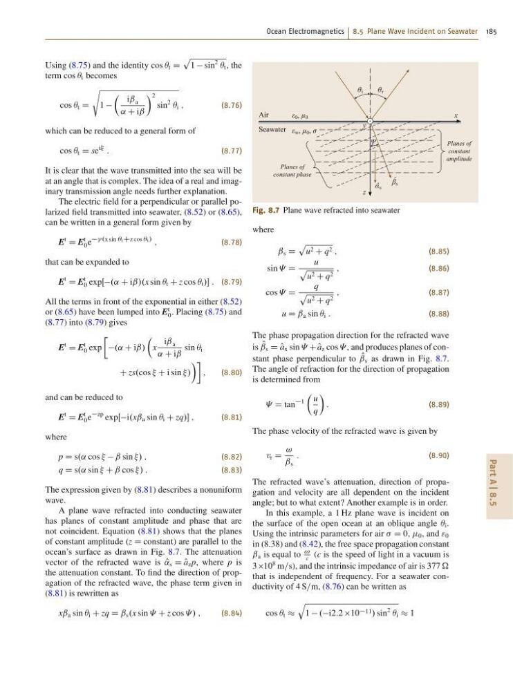
The expression given by (8.81) describes a nonuniform
wave.
A plane wave refracted into conducting seawater
has planes of constant amplitude and phase that are
not coincident. Equation (8.81) shows that the planes
of constant amplitude (z D constant) are parallel to the
ocean’s surface as drawn in Fig. 8.7. The attenuation
vector of the refracted wave is O
˛ s D O
a z p, where p is
the attenuation constant. To find the direction of propagation of the refracted wave, the phase term given in
(8.81) is rewritten as
xˇ a sin  i C zq D ˇ s .x sin « C z cos «/ ;
(8.84)
x
y
z
Air
ε 0 , μ 0
Seawater
Planes of
constant
amplitude
Planes of
constant phase
ε w , μ 0 , σ
θ i
θ r
Ψ
α ˆ s
β ˆ s
Fig. 8.7 Plane wave refracted into seawater
where
ˇ s D
p
u 2 C q 2 ;
(8.85)
sin « D
u
p
u 2 C q 2
;
(8.86)
cos « D
q
p
u 2 C q 2
;
(8.87)
u D ˇ a sin  i :
(8.88)
The phase propagation direction for the refracted wave
is O
ˇ s D O
a x sin « C O
a z cos « , and produces planes of constant phase perpendicular to O
ˇ s as drawn in Fig. 8.7.
The angle of refraction for the direction of propagation
is determined from
« D tan
1
Â
u
q
Ã
:
(8.89)
The phase velocity of the refracted wave is given by
v r D
!
ˇ s
:
(8.90)
The refracted wave’s attenuation, direction of propagation and velocity are all dependent on the incident
angle; but to what extent? Another example is in order.
In this example, a 1 Hz plane wave is incident on
the surface of the open ocean at an oblique angle  i .
Using the intrinsic parameters for air D 0, 0 , and " 0
in (8.38) and (8.42), the free space propagation constant
ˇ a is equal to
!
c
(c is the speed of light in a vacuum is
3 10
8 m=s), and the intrinsic impedance of air is 377
that is independent of frequency. For a seawater conductivity of 4 S=m, (8.76) can be written as
cos  t
q
1 .i2:2 10 11 / sin
2
 i 1
Part A | 8.5
Using (8.75) and the identity cos  t D
p
1 sin
2
 t , the
term cos  t becomes
cos  t D
s
1
 iˇ a
˛ C iˇ
à 2
sin
2
 i ;
(8.76)
which can be reduced to a general form of
cos  t D se
i
:
(8.77)
It is clear that the wave transmitted into the sea will be
at an angle that is complex. The idea of a real and imaginary transmission angle needs further explanation.
The electric field for a perpendicular or parallel polarized field transmitted into seawater, (8.52) or (8.65),
can be written in a general form given by
E
t
D E
t
0 e
.x sin ÂtCz cos Ât/
;
(8.78)
that can be expanded to
E
t
D E
t
0 expŒ.˛ C iˇ/.x sin  t C z cos  t / : (8.79)
All the terms in front of the exponential in either (8.52)
or (8.65) have been lumped into E
t
0 . Placing (8.75) and
(8.77) into (8.79) gives
E
t
D E
t
0 exp
Ä
.˛ C iˇ/
Â
x
iˇ a
˛ C iˇ
sin  i
C zs.cos C i sin /
ÃÃ
;
(8.80)
and can be reduced to
E
t
D E
t
0 e
zp expŒi.xˇ a sin  i C zq/ ;
(8.81)
where
p D s.˛ cos ˇ sin / ;
(8.82)
q D s.˛ sin C ˇ cos / :
(8.83)
The expression given by (8.81) describes a nonuniform
wave.
A plane wave refracted into conducting seawater
has planes of constant amplitude and phase that are
not coincident. Equation (8.81) shows that the planes
of constant amplitude (z D constant) are parallel to the
ocean’s surface as drawn in Fig. 8.7. The attenuation
vector of the refracted wave is O
˛ s D O
a z p, where p is
the attenuation constant. To find the direction of propagation of the refracted wave, the phase term given in
(8.81) is rewritten as
xˇ a sin  i C zq D ˇ s .x sin « C z cos «/ ;
(8.84)
x
y
z
Air
ε 0 , μ 0
Seawater
Planes of
constant
amplitude
Planes of
constant phase
ε w , μ 0 , σ
θ i
θ r
Ψ
α ˆ s
β ˆ s
Fig. 8.7 Plane wave refracted into seawater
where
ˇ s D
p
u 2 C q 2 ;
(8.85)
sin « D
u
p
u 2 C q 2
;
(8.86)
cos « D
q
p
u 2 C q 2
;
(8.87)
u D ˇ a sin  i :
(8.88)
The phase propagation direction for the refracted wave
is O
ˇ s D O
a x sin « C O
a z cos « , and produces planes of constant phase perpendicular to O
ˇ s as drawn in Fig. 8.7.
The angle of refraction for the direction of propagation
is determined from
« D tan
1
Â
u
q
Ã
:
(8.89)
The phase velocity of the refracted wave is given by
v r D
!
ˇ s
:
(8.90)
The refracted wave’s attenuation, direction of propagation and velocity are all dependent on the incident
angle; but to what extent? Another example is in order.
In this example, a 1 Hz plane wave is incident on
the surface of the open ocean at an oblique angle  i .
Using the intrinsic parameters for air D 0, 0 , and " 0
in (8.38) and (8.42), the free space propagation constant
ˇ a is equal to
!
c
(c is the speed of light in a vacuum is
3 10
8 m=s), and the intrinsic impedance of air is 377
that is independent of frequency. For a seawater conductivity of 4 S=m, (8.76) can be written as
cos  t
q
1 .i2:2 10 11 / sin
2
 i 1