

Part A | 8.4
182 Part A Fundamentals
is 1:405 10
3
.1 C i/ / at 1 Hz. The magnitude of
(8.47) has been plotted in Fig. 8.2 for the same parameters as above. As will be shown later, the difference in
impedances between air and the ocean will significantly
affect the reflection and transmission of electromagnetic fields at the sea surface.
As the frequency of the electromagnetic wave increases, so does its velocity. At the top end of the ELF
band, an electromagnetic field propagates more than
100 times faster than sound, but the skin depth decreases to less than 3 m. For this reason, underwater
electromagnetic communication systems for short distance wireless data transfers are preferred over acoustic
modems. In addition, the rapid attenuation of electromagnetic fields in the ocean can be exploited to reduce
interference from nearby transmitters, and for covert
underwater communications systems that must avoid
long range detection.
Another advantage of ULF and ELF electromagnetic fields is their ability to cross the air–ocean boundary. The description of plane wave transmission from
air into conducting seawater is more complex than for
fresh water. Therefore, the formulation of the reflection
and transmission coefficients at the sea surface will begin with that of a plane wave incident on fresh water,
such as a lake.
8.4 Reflection and Transmission of a Plane Wave at the Surface
of Fresh Water
The reflection and transmission coefficients of a plane
wave at the surface of fresh water depend on the polarization of the incident field. If the electric field vector of
the incident uniform plane wave is perpendicular to the
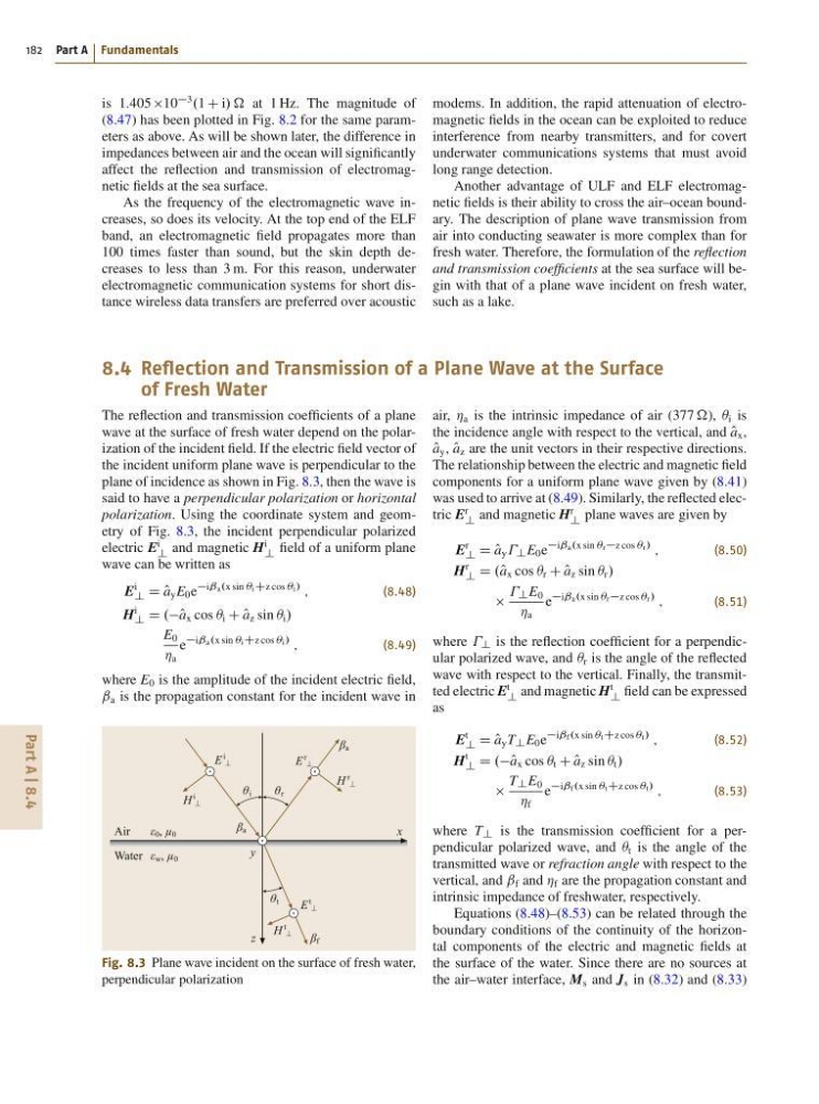
plane of incidence as shown in Fig. 8.3, then the wave is
said to have a perpendicular polarization or horizontal
polarization. Using the coordinate system and geometry of Fig. 8.3, the incident perpendicular polarized
electric E
i
? and magnetic H
i
? field of a uniform plane
wave can be written as
E
i
? D O
a y E 0 e
iˇa.x sin ÂiCz cos Âi/
;
(8.48)
H
i
? D .O a x cos  i C O
a z sin  i /
E 0
Á a
e
iˇa.x sin ÂiCz cos Âi/
;
(8.49)
where E 0 is the amplitude of the incident electric field,
ˇ a is the propagation constant for the incident wave in
x
y
z
Air
ε 0 , μ 0
Water ε w , μ 0
E
i
E
r
E
t
H
i
H
r
H
t
θ i
θ r
θ t
β f
β a
β a
Fig. 8.3 Plane wave incident on the surface of fresh water,
perpendicular polarization
air, Á a is the intrinsic impedance of air (377 ), Â i is
the incidence angle with respect to the vertical, and O
a x ,
O
a y , O
a z are the unit vectors in their respective directions.
The relationship between the electric and magnetic field
components for a uniform plane wave given by (8.41)
was used to arrive at (8.49). Similarly, the reflected electric E
r
? and magnetic H
r
? plane waves are given by
E
r
? D O
a y ? E 0 e
iˇa.x sin Ârz cos Âr/
;
(8.50)
H
r
? D .O a x cos  r C O
a z sin  r /
? E 0
Á a
e
iˇa.x sin Ârz cos Âr/
;
(8.51)
where ? is the reflection coefficient for a perpendicular polarized wave, and  r is the angle of the reflected
wave with respect to the vertical. Finally, the transmitted electric E
t
? and magnetic H
t
? field can be expressed
as
E
t
? D O
a y T ? E 0 e
iˇf.x sin ÂtCz cos Ât/
;
(8.52)
H
t
? D .O a x cos  t C O
a z sin  t /
T ? E 0
Á f
e
iˇf.x sin ÂtCz cos Ât/
;
(8.53)
where T ? is the transmission coefficient for a perpendicular polarized wave, and  t is the angle of the
transmitted wave or refraction angle with respect to the
vertical, and ˇ f and Á f are the propagation constant and
intrinsic impedance of freshwater, respectively.
Equations (8.48)–(8.53) can be related through the
boundary conditions of the continuity of the horizontal components of the electric and magnetic fields at
the surface of the water. Since there are no sources at
the air–water interface, M s and J s in (8.32) and (8.33)
182 Part A Fundamentals
is 1:405 10
3
.1 C i/ / at 1 Hz. The magnitude of
(8.47) has been plotted in Fig. 8.2 for the same parameters as above. As will be shown later, the difference in
impedances between air and the ocean will significantly
affect the reflection and transmission of electromagnetic fields at the sea surface.
As the frequency of the electromagnetic wave increases, so does its velocity. At the top end of the ELF
band, an electromagnetic field propagates more than
100 times faster than sound, but the skin depth decreases to less than 3 m. For this reason, underwater
electromagnetic communication systems for short distance wireless data transfers are preferred over acoustic
modems. In addition, the rapid attenuation of electromagnetic fields in the ocean can be exploited to reduce
interference from nearby transmitters, and for covert
underwater communications systems that must avoid
long range detection.
Another advantage of ULF and ELF electromagnetic fields is their ability to cross the air–ocean boundary. The description of plane wave transmission from
air into conducting seawater is more complex than for
fresh water. Therefore, the formulation of the reflection
and transmission coefficients at the sea surface will begin with that of a plane wave incident on fresh water,
such as a lake.
8.4 Reflection and Transmission of a Plane Wave at the Surface
of Fresh Water
The reflection and transmission coefficients of a plane
wave at the surface of fresh water depend on the polarization of the incident field. If the electric field vector of
the incident uniform plane wave is perpendicular to the
plane of incidence as shown in Fig. 8.3, then the wave is
said to have a perpendicular polarization or horizontal
polarization. Using the coordinate system and geometry of Fig. 8.3, the incident perpendicular polarized
electric E
i
? and magnetic H
i
? field of a uniform plane
wave can be written as
E
i
? D O
a y E 0 e
iˇa.x sin ÂiCz cos Âi/
;
(8.48)
H
i
? D .O a x cos  i C O
a z sin  i /
E 0
Á a
e
iˇa.x sin ÂiCz cos Âi/
;
(8.49)
where E 0 is the amplitude of the incident electric field,
ˇ a is the propagation constant for the incident wave in
x
y
z
Air
ε 0 , μ 0
Water ε w , μ 0
E
i
E
r
E
t
H
i
H
r
H
t
θ i
θ r
θ t
β f
β a
β a
Fig. 8.3 Plane wave incident on the surface of fresh water,
perpendicular polarization
air, Á a is the intrinsic impedance of air (377 ), Â i is
the incidence angle with respect to the vertical, and O
a x ,
O
a y , O
a z are the unit vectors in their respective directions.
The relationship between the electric and magnetic field
components for a uniform plane wave given by (8.41)
was used to arrive at (8.49). Similarly, the reflected electric E
r
? and magnetic H
r
? plane waves are given by
E
r
? D O
a y ? E 0 e
iˇa.x sin Ârz cos Âr/
;
(8.50)
H
r
? D .O a x cos  r C O
a z sin  r /
? E 0
Á a
e
iˇa.x sin Ârz cos Âr/
;
(8.51)
where ? is the reflection coefficient for a perpendicular polarized wave, and  r is the angle of the reflected
wave with respect to the vertical. Finally, the transmitted electric E
t
? and magnetic H
t
? field can be expressed
as
E
t
? D O
a y T ? E 0 e
iˇf.x sin ÂtCz cos Ât/
;
(8.52)
H
t
? D .O a x cos  t C O
a z sin  t /
T ? E 0
Á f
e
iˇf.x sin ÂtCz cos Ât/
;
(8.53)
where T ? is the transmission coefficient for a perpendicular polarized wave, and  t is the angle of the
transmitted wave or refraction angle with respect to the
vertical, and ˇ f and Á f are the propagation constant and
intrinsic impedance of freshwater, respectively.
Equations (8.48)–(8.53) can be related through the
boundary conditions of the continuity of the horizontal components of the electric and magnetic fields at
the surface of the water. Since there are no sources at
the air–water interface, M s and J s in (8.32) and (8.33)