

Part A | 7.3
168 Part A Fundamentals
p
dx
2
C dy
2 e
i , respectively (Fig. 7.75). Therefore,
the product of these two terms can be rewritten
as
.u C iv /dN z D
p
u 2 C v 2 e
iÂ
q
dx
2
C dy
2 e
iÂ
D
p
u 2 C v 2 e
iÂ
q
dx
2
C dy
2 e
iÂ
D .u iv /dz :
Then the integral becomes
D iL D
i
2
I
C
.u iv /
2 dz D
i
2
I
C
 dw
dz
à 2
dz :
(7.67)
Use of this integral is known as the Blasius theorem for
calculating the lift and drag on a body of any crosssectional shape in a steady, two-dimensional, incompressible, irrotational flow. The contour integral does
not need to be taken at the surface of the body – so long
as there are no singularities (e.g., sources/sinks, irrotational vortices, etc.) between the body and C (Fig. 7.76).
At a very large distance from the body all singularities appear to be located at z D 0. We can use series
(u + iυ)
d z
d z
d z
–
(u + iυ)
(u – iυ)
Surface
Fig. 7.75 As the flow is everywhere tangent to the surface,
.u C iv / and dz are in the same direction. The reflection
of these complex vectors about the horizontal axis gives
.u iv / and dN z
R
C
Fig. 7.76 Contour integral about a body in a flow to evaluate the Blasius integral
expansions to simplify the Blasius integral in this case
using the Residue Theorem.
Example 7.10
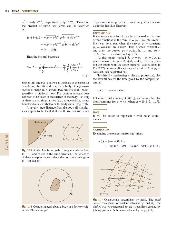
If the stream function can be expressed as the sum
of two functions in the form D 1 C 2 , the streamlines can be drawn when the curves 1 D constant,
2 D constant are known. Take a small constant !
and draw the curves 1 D !; 2!; 3!; : : : and 2 D
!; 2!; 3!; : : : as shown in Fig. 7.77.
At the points marked 3,
D 1 C 2 D 3!, at
points marked 4,
D 1 C 2 D 4!, etc. By joining the points with the same numeral (dashed lines in
Fig. 7.77) the streamlines, along which D 1 C 2 D
constant, can be plotted out.
Try this. By hand (using a ruler and protractor), plot
the streamlines for the flow given by the complex potential
w .z/ D .m C ik/ ln z :
Let m D 1, and k D 7 ln.10/, and ! D =4. Plot
the streamlines for D n!, where n D f0; 1; 2; : : :; 7g.
Note
It will be easier to represent z with polar coordinates r; Â.
Solution 7.9
Expanding the expression for w .z/ gives
w .z/ D .m C ik/ ln z
D D.m ln r C kÂ/ C i.k ln r mÂ/ D C i :
ω
2ω
3ω
3ω
2ω
2
3
4
5
6
5
4
3
4
5
6
7
8
7
6
5
4ω
ψ 2 = 4ω
ψ 1 = ω
Fig. 7.77 Constructing streamlines by hand. The solid
curves correspond to constant values of 1 and 2 . The
dashed curves correspond to the streamlines created by
joining points with the same values of D 1 C 2
168 Part A Fundamentals
p
dx
2
C dy
2 e
i , respectively (Fig. 7.75). Therefore,
the product of these two terms can be rewritten
as
.u C iv /dN z D
p
u 2 C v 2 e
iÂ
q
dx
2
C dy
2 e
iÂ
D
p
u 2 C v 2 e
iÂ
q
dx
2
C dy
2 e
iÂ
D .u iv /dz :
Then the integral becomes
D iL D
i
2
I
C
.u iv /
2 dz D
i
2
I
C
 dw
dz
à 2
dz :
(7.67)
Use of this integral is known as the Blasius theorem for
calculating the lift and drag on a body of any crosssectional shape in a steady, two-dimensional, incompressible, irrotational flow. The contour integral does
not need to be taken at the surface of the body – so long
as there are no singularities (e.g., sources/sinks, irrotational vortices, etc.) between the body and C (Fig. 7.76).
At a very large distance from the body all singularities appear to be located at z D 0. We can use series
(u + iυ)
d z
d z
d z
–
(u + iυ)
(u – iυ)
Surface
Fig. 7.75 As the flow is everywhere tangent to the surface,
.u C iv / and dz are in the same direction. The reflection
of these complex vectors about the horizontal axis gives
.u iv / and dN z
R
C
Fig. 7.76 Contour integral about a body in a flow to evaluate the Blasius integral
expansions to simplify the Blasius integral in this case
using the Residue Theorem.
Example 7.10
If the stream function can be expressed as the sum
of two functions in the form D 1 C 2 , the streamlines can be drawn when the curves 1 D constant,
2 D constant are known. Take a small constant !
and draw the curves 1 D !; 2!; 3!; : : : and 2 D
!; 2!; 3!; : : : as shown in Fig. 7.77.
At the points marked 3,
D 1 C 2 D 3!, at
points marked 4,
D 1 C 2 D 4!, etc. By joining the points with the same numeral (dashed lines in
Fig. 7.77) the streamlines, along which D 1 C 2 D
constant, can be plotted out.
Try this. By hand (using a ruler and protractor), plot
the streamlines for the flow given by the complex potential
w .z/ D .m C ik/ ln z :
Let m D 1, and k D 7 ln.10/, and ! D =4. Plot
the streamlines for D n!, where n D f0; 1; 2; : : :; 7g.
Note
It will be easier to represent z with polar coordinates r; Â.
Solution 7.9
Expanding the expression for w .z/ gives
w .z/ D .m C ik/ ln z
D D.m ln r C kÂ/ C i.k ln r mÂ/ D C i :
ω
2ω
3ω
3ω
2ω
2
3
4
5
6
5
4
3
4
5
6
7
8
7
6
5
4ω
ψ 2 = 4ω
ψ 1 = ω
Fig. 7.77 Constructing streamlines by hand. The solid
curves correspond to constant values of 1 and 2 . The
dashed curves correspond to the streamlines created by
joining points with the same values of D 1 C 2