

Hydromechanics 7.3 Hydrodynamics 157
Part A | 7.3
Conservation of Momentum
This is basically a statement of Newton’s second law in
a fluid flow. Mass per unit volume multiplied by fluid
acceleration (the material derivative of the velocity) is
the sum of applied forces. In an incompressible fluid,
the applied forces can consist of viscous shear and pressure acting at the surface of a fluid element, or body
forces acting on the volume of the fluid element, giving
du
dt
„ƒ‚…
mass acceleration
D Dr p C r
2 u
„
ƒ‚
…
pressure and viscous forces
C g
„ƒ‚…
body forces
„
ƒ‚
…
applied external forces
:
(7.56)
The integral form of conservation of momentum in
the volume V (Fig. 7.50) can be written as
@
@t
Z
V
udV
„ ƒ‚ …
time rate of change
of momentum in V
C
Z
S
u.u dS/
„ ƒ‚ …
flux of momentum
into or out of V
D
Z
V
gdV
„ ƒ‚ …
body forces
C
Z
S
dS
„ ƒ‚ …
pressure and viscous
stress terms
„
ƒ‚
…
applied external forces
;
(7.57)
where is the second-order stress tensor
Á pI C Œr u C .r u/
T
;
(7.58)
I is the identity matrix, T denotes the transpose, and
r u is the gradient of the velocity vector (also a secondorder tensor).
The integral form of the conservation laws is generally used when one is trying to determine the effect of
a volume of flow. The differential forms are used when
trying to determine the distribution of quantities, such
as velocity or pressure within a flow.
ρuu
dS = n ˆdS
n ˆ = Surface normal
dS = Element of area
S = Total surface area
Momentum flux
V
Fig. 7.50 Fluid volume V for formulation of momentum
conservation
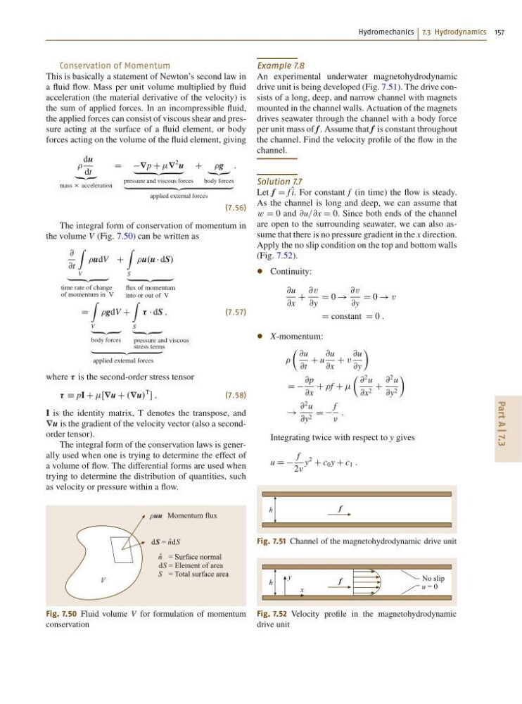
Example 7.8
An experimental underwater magnetohydrodynamic
drive unit is being developed (Fig. 7.51). The drive consists of a long, deep, and narrow channel with magnets
mounted in the channel walls. Actuation of the magnets
drives seawater through the channel with a body force
per unit mass of f . Assume that f is constant throughout
the channel. Find the velocity profile of the flow in the
channel.
Solution 7.7
Let f D f O i. For constant f (in time) the flow is steady.
As the channel is long and deep, we can assume that
w D 0 and @u=@x D 0. Since both ends of the channel
are open to the surrounding seawater, we can also assume that there is no pressure gradient in the x direction.
Apply the no slip condition on the top and bottom walls
(Fig. 7.52).
Continuity:
@u
@x
C
@v
@y
D 0 !
@v
@y
D 0 ! v
D constant D 0 :
X-momentum:
 @u
@t
C u
@u
@x
C v
@u
@y
Ã
D D
@p
@x
C f C
 @
2 u
@x 2 C
@
2 u
@y 2
Ã
!
@
2 u
@y 2 D D
f
:
Integrating twice with respect to y gives
u D D
f
2
y
2
C c 0 y C c 1 :
f
h
Fig. 7.51 Channel of the magnetohydrodynamic drive unit
f
h
y
x
No slip
u = 0
Fig. 7.52 Velocity profile in the magnetohydrodynamic
drive unit
Part A | 7.3
Conservation of Momentum
This is basically a statement of Newton’s second law in
a fluid flow. Mass per unit volume multiplied by fluid
acceleration (the material derivative of the velocity) is
the sum of applied forces. In an incompressible fluid,
the applied forces can consist of viscous shear and pressure acting at the surface of a fluid element, or body
forces acting on the volume of the fluid element, giving
du
dt
„ƒ‚…
mass acceleration
D Dr p C r
2 u
„
ƒ‚
…
pressure and viscous forces
C g
„ƒ‚…
body forces
„
ƒ‚
…
applied external forces
:
(7.56)
The integral form of conservation of momentum in
the volume V (Fig. 7.50) can be written as
@
@t
Z
V
udV
„ ƒ‚ …
time rate of change
of momentum in V
C
Z
S
u.u dS/
„ ƒ‚ …
flux of momentum
into or out of V
D
Z
V
gdV
„ ƒ‚ …
body forces
C
Z
S
dS
„ ƒ‚ …
pressure and viscous
stress terms
„
ƒ‚
…
applied external forces
;
(7.57)
where is the second-order stress tensor
Á pI C Œr u C .r u/
T
;
(7.58)
I is the identity matrix, T denotes the transpose, and
r u is the gradient of the velocity vector (also a secondorder tensor).
The integral form of the conservation laws is generally used when one is trying to determine the effect of
a volume of flow. The differential forms are used when
trying to determine the distribution of quantities, such
as velocity or pressure within a flow.
ρuu
dS = n ˆdS
n ˆ = Surface normal
dS = Element of area
S = Total surface area
Momentum flux
V
Fig. 7.50 Fluid volume V for formulation of momentum
conservation
Example 7.8
An experimental underwater magnetohydrodynamic
drive unit is being developed (Fig. 7.51). The drive consists of a long, deep, and narrow channel with magnets
mounted in the channel walls. Actuation of the magnets
drives seawater through the channel with a body force
per unit mass of f . Assume that f is constant throughout
the channel. Find the velocity profile of the flow in the
channel.
Solution 7.7
Let f D f O i. For constant f (in time) the flow is steady.
As the channel is long and deep, we can assume that
w D 0 and @u=@x D 0. Since both ends of the channel
are open to the surrounding seawater, we can also assume that there is no pressure gradient in the x direction.
Apply the no slip condition on the top and bottom walls
(Fig. 7.52).
Continuity:
@u
@x
C
@v
@y
D 0 !
@v
@y
D 0 ! v
D constant D 0 :
X-momentum:
 @u
@t
C u
@u
@x
C v
@u
@y
Ã
D D
@p
@x
C f C
 @
2 u
@x 2 C
@
2 u
@y 2
Ã
!
@
2 u
@y 2 D D
f
:
Integrating twice with respect to y gives
u D D
f
2
y
2
C c 0 y C c 1 :
f
h
Fig. 7.51 Channel of the magnetohydrodynamic drive unit
f
h
y
x
No slip
u = 0
Fig. 7.52 Velocity profile in the magnetohydrodynamic
drive unit